
Valve implanting device

a valve and implanting technology, applied in the field of prosthetic implants, can solve the problems of sudden loss of blood supply to immediate malfunction of the affected body organ, and inability to valve, etc., to achieve the effect of reducing thrombosis, reducing stenosis, and improving durability

Active Publication Date: 2005-10-04
SRIVASTAVA ROHIT
View PDF56 Cites 638 Cited by
  • Summary
  • Abstract
  • Description
  • Claims
  • Application Information

AI Technical Summary

Benefits of technology

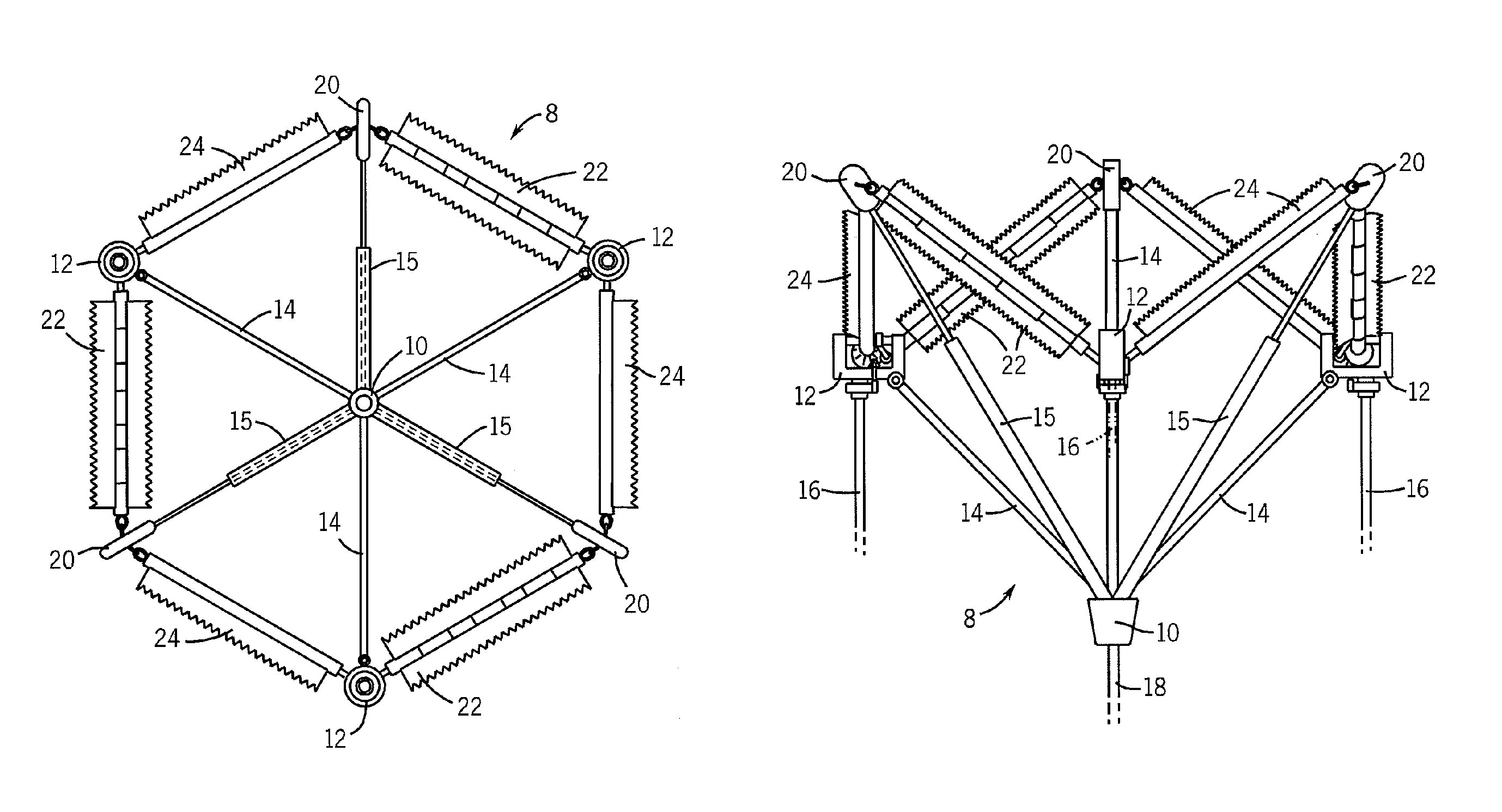
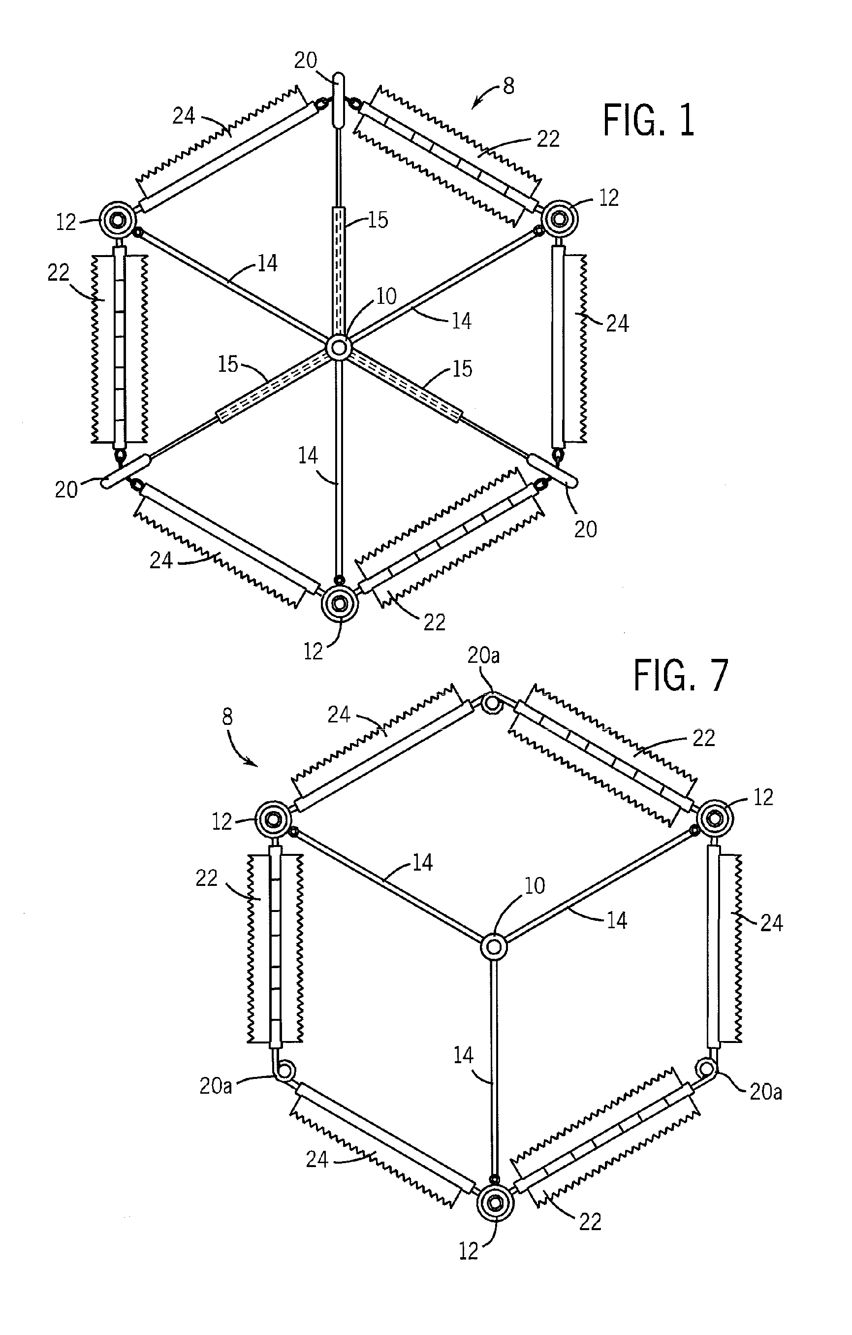
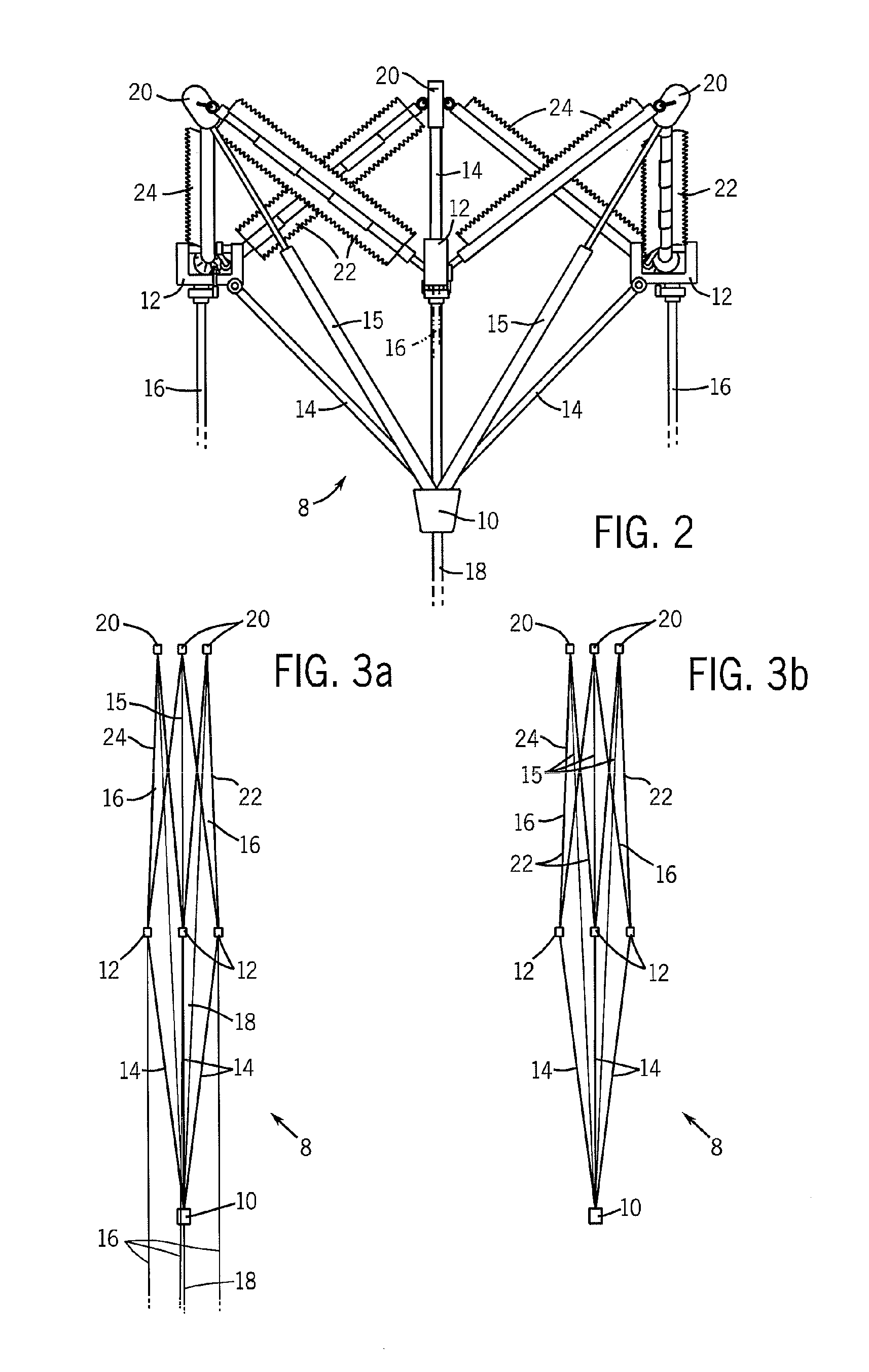
[0054]The present invention further contemplates a method for implanting a valve device. The method includes the steps of providing a valve implanting device according to the present invention, collapsing the device about the central hub, inserting the device into a patient's vein or artery, positioning the device in a desired deployment location, expanding the device about the central hub, and stabilizing the device in the desired deployment location.
[0055]Advantages and objectives of the present invention include reduced stenosis, ease of heart valve replacement, improved durability, hemodynamic performance, reduced thrombogenicity, relative ease of surgical implantation with minimally invasive techniques, reduced failure rate, appropriate anchoring and positioning means, improved anticoagulation properties, without noisy operations.

Problems solved by technology

Problems that can develop with heart valves consist of stenosis, in which a valve does not open properly, and / or insufficiency, also called regurgitation, in which a valve does not close properly.
In addition to stenosis and insufficiency of heart valves, heart valves may need to be surgically repaired or replaced due to certain types of bacterial or fungal infections in which the valve may continue to function normally, but nevertheless harbors an overgrowth of bacteria (vegetation) on the leaflets of the valve that may embolize and lodge downstream in a vital artery.
If such vegetations are on the valves of the left side (i.e., the systemic circulation side) of the heart, embolization may occur, resulting in sudden loss of the blood supply to the affected body organ and immediate malfunction of that organ.
Likewise, bacterial or fungal vegetations on the tricuspid valve may embolize to the lungs resulting in a lung abscess and therefore, may require replacement of the tricuspid valve even though no tricuspid valve stenosis or insufficiency is present.
These problems are sometimes treated by surgical repair of valves, unless, as is often the case, the valves are too diseased to repair and must be replaced.
Mechanical valves are typically constructed from nonbiological materials such as plastics, metals and other artificial materials which, while durable, are expensive and prone to cause blood clotting which increases the risk of an embolism.
Anticoagulants taken to reduce the risk of blood clotting can further complicate the patient's health by increasing the risk of hemorrhage.
The major disadvantage of tissue valves is that they lack the long-term durability of mechanical valves.
Tissue valves have a significant failure rate, usually within ten years following implantation.
One cause of these failures is believed to be the chemical treatment of the animal tissue that prevents it from being antigenic to the patient.
In addition, the presence of extensive suturing prevents the artificial tissue valve from being anatomically accurate in comparison to a normal heart valve, even in the aortic valve position.
A shortcoming of prior artificial tissue valves has been the inability to effectively simulate the exact anatomy of a native heart valve.
Additionally, the leaflets of most such tissue valves are constructed by cutting or suturing the tissue material, resulting in leaflets that do not duplicate the form and function of a real valve.
Although replacement valves and surgical procedures have been developed to alleviate these conditions, they have significant drawbacks.
These invasive techniques are stressful on the patient, and increase the opportunity for infection and slow recovery.
However, many of these valves also require the damaged native heart valve be removed prior to implanting the artificial valve.
Removing the native valve increases the risk that a portion of the valve will migrate through the body and block vessels downstream from the heart.
Further, the Andersen device requires a separate inflating balloon for its deployment.
By its very nature, however, a U-shaped stenting element may not be easily compressible inside catheter tubing.
Further, peripheral anchors attached to the frame may collapse or be dislodged, causing undesirable blood flow, or lack of blood flow altogether.
This band is made of biocompatible material, which may cause undesirable thrombogenesis.
However, the size of the Pavcnik device makes percutaneous implantation difficult.
In absence of anchoring devices however, accurate placement and holding in a given position is difficult.
With these valve prostheses therefore it is impossible for a patient resume a substantially normal life.
However, this valve prosthesis is not designed for implantation in the body by catheterization.
The device presents significant hemodynamic, delivery, fatigue and stability disadvantages.
Specifically, the device and method put forth will require a 20+ French size catheter (approximately 9 French sizes to accommodate the balloon and 14+ French sizes to accommodate the compressed device) making the device clinically ineffective as a minimally invasive technique.
Additionally, the device does not adequately address hemodynamic, stability and anchoring concerns.
The disadvantages of the device are that the flow regulators reduce the effective valve orifice and generate sub-optimal hemodynamic characteristics; fatigue concerns arise from the separate nature of the stent and flow-regulation components; the high metal and exposed metal content increase thrombogenesis, valvular stenosis and chronic anticoagulation concerns; and the separate delivery requirements (although addressing the need for small delivery profile) in addition to any initial valvuloplasty performed increases the time, costs, risks, difficulty and trauma associated with the percutaneous procedure.
The devices disclosed indicate a long and complex procedure requiring large diameter catheters.
The valve device disclosed will require a large delivery catheter and does not address the key mechanisms required of a functioning valve.
The disadvantages of this design include a lack of a sufficient anchoring mechanism; problematic interference concerns with adjacent tissues and anatomical structures; fatigue concerns associated with the multiplicity of segments, connections and sutures; lack of an adequately controlled and biased flow-regulation mechanism; an uncertain effective valve orifice; difficult manufacture; balloon dilation requirement; complex, difficult and inaccurate delivery and large delivery profile.
The disadvantages of the device are a lack of a well defined and biased flow regulation mechanism; a requirement of anatomic valve removal thereby lengthening the procedure time, increasing difficulty and reducing clinical practicality; trauma induced by the barbs as described above; and the instability of the device and the likelihood of migration if the barbs are omitted.
The disadvantages of this design include problematic interactions between the stent and flaps in the delivery state, lack of clinical data on coiled stent performance, the lack of a detailed mechanism to ensure that the flaps will create a competent one-directional valve, lack of appropriate anchoring means, and the fact that the design requirements imposed by surrounding anatomical structures are ignored.
The disadvantages of the device include the small effective valve orifice of the flow regulation mechanism, the turbidity caused by the multiple slit mechanisms, the large delivery profile required by the disclosed embodiments, and the lack of acute anchoring means.
Disadvantages of this device include those profile concerns associated with biological valves and unsupported graft-leaflet regulators, a large diameter complex delivery system and method which requires multiple anchoring balloons and the use of a light activated tissue adhesive in addition to any prior valvuloplasty performed, interference with surrounding anatomy and the questionable clinical utility and feasibility of the light activated adhesive.
Some of the main disadvantages of these devices include a need for permanent treatment by use of anticoagulants, noisy operation, and the need for a large-scale operation to implant.

Method used


Image

  • Valve implanting device
  • Valve implanting device
  • Valve implanting device

Examples


Embodiment Construction

[0071]The present invention provides a prosthetic arterial or venous valve implant which is capable of being delivered using endovascular techniques and may be implanted at an intraarterial, intracardiac or intravenous site without the need for an open surgical procedure. While, the invention is preferably described for implantation via a catheter, the device may also be implanted via open-heart procedures, as described above.

[0072]In a preferred embodiment, the present invention provides an arterial valve implant device. In a more preferred embodiment the device is an aortic valve implant. Furthermore, while the device has been described in terms of the most preferred embodiment of an aortic valve implant, one of the ordinary skill in the art, may use and construct this device for use as any arterial or venous valve implant, without departing from the scope of the invention.

[0073]The prosthetic valves of the present invention are well-suited for cardiac delivery via a femoral or su...


PUM


Abstract

Disclosed is a valve implanting device comprising a collapsible frame, inner and outer guide wires removably connected to the collapsible frame, and a plurality of valve flaps attached to the collapsible frame. The collapsible frame is inserted into a patient's femoral vein or artery, guided to a deployment position using the guide wires, expanded using the guide wires, and stabilized using the guide wires to manipulate fixating hubs on the collapsible frame. The collapsible frame includes a central hub, a plurality of spokes, fixating hubs, gripping members, and a plurality of valve flaps.

Description

BACKGROUND OF THE INVENTION[0001]The present invention relates generally to the field of prosthetic implants, and more particularly to valve implants and methods related thereto.[0002]Valve implants are useful in repairing and introducing desirable blood flow patterns in animal systems. Valve prostheses are usually implanted in one of the channels of the body to replace a natural valve. In particular, heart implants are useful in repairing or replacing damaged heart valves.[0003]As described in the U.S. Pat. No. 6,540,782 to Snyders and U.S. Patent Application 2003 / 0130729 to Paniagua et al., a human heart has four chambers which alternately expand and contract to pump blood through the vessels of the body. There are four valves in the human heart that serve to direct the flow of blood through the two sides of the heart in a forward direction. On the left (systemic) side of the heart are: 1) the mitral valve, located between the left atrium and the left ventricle, and 2) the aortic ...

Claims


Application Information

Patent Timeline
IPC IPC(8): A61F2/06A61F2/24
CPCA61F2/2418A61F2/243A61F2/2475A61F2220/005A61F2220/0016
Inventor SRIVASTAVA, ROHIT
Owner SRIVASTAVA ROHIT
Learn More