
Anti-reflection film material and a substrate having an anti-reflection film and a method for forming a pattern

a technology of anti-reflection film and substrate, which is applied in the field of anti-reflection film material, can solve the problems of resist pattern turning into a taper, pattern dimension variation, standing wave generation, etc., and achieves the effect of high processing efficiency, sufficient reflection prevention effect, and high accuracy

Active Publication Date: 2007-01-16
SHIN ETSU CHEM IND CO LTD
View PDF39 Cites 28 Cited by
  • Summary
  • Abstract
  • Description
  • Claims
  • Application Information

AI Technical Summary

Benefits of technology

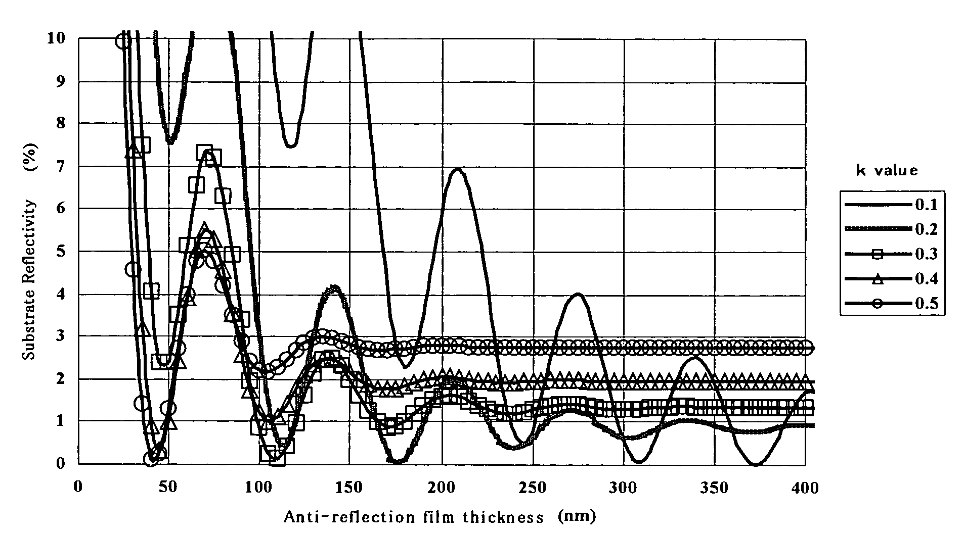
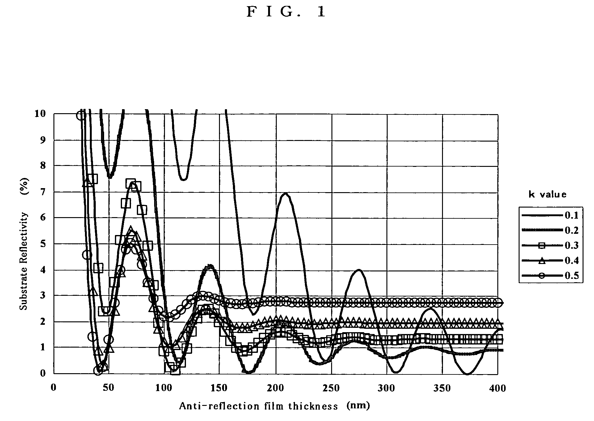
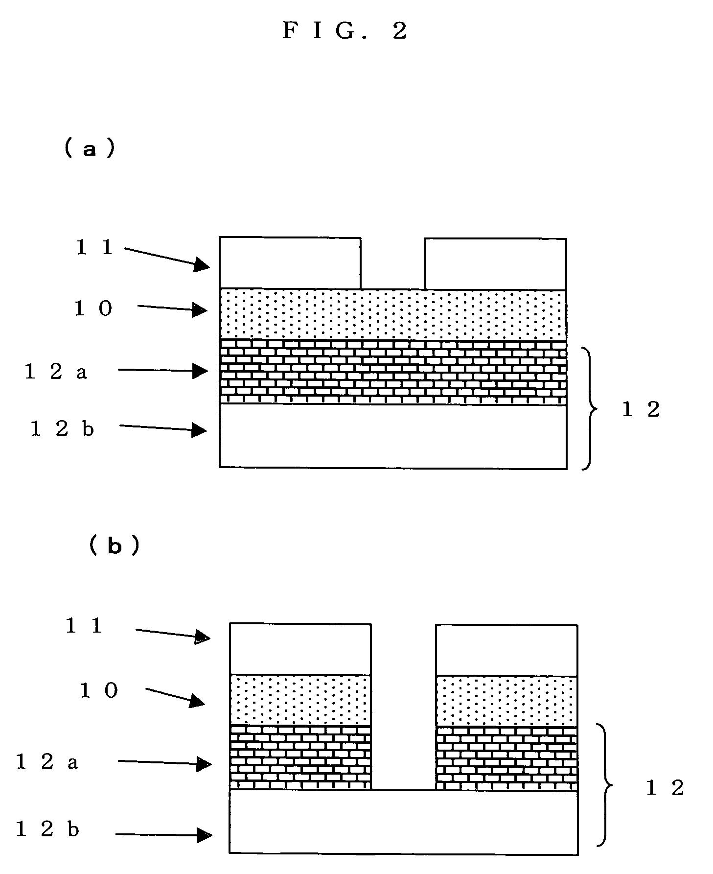
[0023]The present invention has been made in order to solve such problems. The object of the present invention is to provide an anti-reflection film material which has an excellent reflection preventive effect to exposure at short wavelength, and has high etch selectivity, namely, an etch rate is higher enough than the photoresist film, an etch rate is sufficiently slower than a substrate to be processed, wherein the shape of the resist pattern formed in the photoresist film on the anti-reflection film can be made perpendicular, and to provide a method of forming a pattern on a substrate using the anti-reflection film material.

Problems solved by technology

However, the combination of the narrow spectrum laser light and the refracting-optical-system lens has been dominant, since an accuracy of the achromatic lens or an aspherical surface reflecting optical system is not enough.
Generally, it is a phenomenon which has been known well for many years that the incident light and reflected light from a substrate interfere with each other in exposure with a single wavelength, which may lead to generation of a standing wave.
However, there was caused a problem that a shape of the resist pattern turns into a taper in the method of adding a light absorber.
As a wavelength gets shorter and a pattern gets finer in recent years, the problem of variation of pattern dimension due to the standing wave and the halation has become serious, and it has become impossible to fully solve the problem by the method of adding a light absorber.
In the method of covering the upper surface of the photoresist film with the anti-reflection film, the anti-reflection film (hereafter referred to as the upper layer transmission type anti-reflection film) is effective only in reduction of a standing wave in principle, and it is not effective in the halation.
In ArF lithography, the effectiveness of the upper layer transmission type anti-reflection film can hardly be expected for the reason for the above, and also in KrF lithography, control of a line width becomes severe because of further decrease of the line width in future.
However, if the molecular weight of the base resin becomes high in this case, there may be caused a problem that a pinhole is easily generated after spin coating, a problem that it becomes impossible to be filtered, a problem that viscosity change will be caused with time and a thickness will be varied, and a problem that a crystal is deposited at a tip of a nozzle.
However, since it is hardly exfoliated, application thereof is limited.
Moreover, since it contains a nitrogen atom and is basic, there is also a disadvantage that the footing profile is likely caused in the case of a positive resist, and an undercut profile is easily caused in the case of a negative resist.
However, since many of the light absorbers have an aromatic group or a double bond, dry etch resistance is raised by addition of the light absorber, and there is a disadvantages that a dry etch selectivity to the photoresist film is not so high.
Furthermore, there is also a problem that a thickness of the anti-reflection film needs to be increased, as explained above.
Accordingly, even if a polymer having low etching resistance such as an acrylic resin is used as a polymer backbone from which a die is suspended, there is a practical limit.
Although the improvement in etching resistance of the photoresist film is needed as a film gets thin, it is not enough at present.
However, since it has a similar composition of elements to SiO2, there is a disadvantage that the etch selectivity which is an original function as a hard mask is low.

Method used


Image

  • Anti-reflection film material and a substrate having an anti-reflection film and a method for forming a pattern
  • Anti-reflection film material and a substrate having an anti-reflection film and a method for forming a pattern
  • Anti-reflection film material and a substrate having an anti-reflection film and a method for forming a pattern

Examples


preparation example 1

[0157]23.6 g of 3-glycidoxy propyl trimethoxy silane, 19.8 g of phenyl trimethoxy silane, and 22.3 g of 3-acetoxypropyltri methoxy silane were dissolved in 200 g of tetrahydrofuran (THF) and 100 g of pure water, and a liquid temperature was made into 35° C. Then, 21 g of 37% hydrochloric acid water was dropped over 1 hour, and then a temperature was raised to 64° C., to perform a condensation reaction of silanol, a ring-opening reaction of an epoxy group and an addition reaction of hydrochloric acid.

[0158]200 g of diethyl ether was added to the above-mentioned reaction mixture, and the water phase was separated from the organic phase. The organic phase was washed twice with ultrapure water, and then 200 g of propylene-glycol-monomethyl-ether acetate (PGMEA) was added thereto. THF and diethyl ether water were removed under the reduced pressure with heating a liquid temperature at 60° C., and thereby Polymer 1 shown below was obtained.

[0159]

[0160]The molecular weight (Mw) as converted...

preparation example 2

[0162]23.6 g of 3-glycidoxy propyl trimethoxy silane, 19.8 g of phenyl trimethoxy silane, and 22.3 g of 3-acetoxypropyl trimethoxy silane were dissolved in 200 g of tetrahydrofuran and 100 g of pure water, and a liquid temperature was made to 35° C. Then, 9.6 g of 70% nitric acid was dropped over 1 hour, and then the temperature was raised to 64° C., to perform a condensation reaction of silanol and a ring-opening reaction of an epoxy group.

[0163]200 g of diethyl ether was added to the above-mentioned reaction mixture, and the water phase was separated from the organic phase. The organic phase was washed twice with ultrapure water, and then 200 g of propylene-glycol-monomethyl-ether acetate (PGMEA) were added thereto. THF and diethyl ether water were removed under the reduced pressure with heating the liquid temperature at 60° C., and thereby the Polymer 2 shown below was obtained.

[0164]

[0165]The molecular weight (Mw) as converted to polystyrene was calculated by gel permeation chro...

preparation example 3

[0167]24.6 g of 2-(3,4-epoxy cyclohexyl)ethyl trimethoxy silane, 19.8 g of phenyl trimethoxy silane, and 17.2 g of 2-cyano ethyl trimethoxy silane were dissolved in 200 g of tetrahydrofuran and 100 g of pure water, and a liquid temperature was made to 35° C. Then 1.7 g of tetramethyl ammonium hydroxide was added, and then the temperature was raised to 60° C., to perform a condensation reaction of silanol.

[0168]200 g of diethyl ether was added to the above-mentioned reaction mixture, the water phase was separated from the organic phase. The organic phase was washed twice with 1% aqueous acetic acid and ultrapure water, and then 200 g of propylene-glycol-monomethyl-ether acetate (PGMEA) was added thereto. THF and diethyl ether water were removed under the reduced pressure with heating liquid temperature at 60° C., and thereby Polymer 3 shown below was obtained.

[0169]

[0170]The molecular weight (Mw) as converted to polystyrene was calculated by the gel permeation chromatography (GPC), a...


PUM

PropertyMeasurementUnit
Lightaaaaaaaaaa
Selectivityaaaaaaaaaa
Etch rateaaaaaaaaaa

Abstract

There is disclosed an anti-reflection film material used in lithography containing at least a polymer compound having repeating units for copolymerization represented by the following general formula (1), or those containing a polymer compound having repeating units for copolymerization represented by the following general formula (2) and a polymer compound having repeating units for copolymerization represented by the following general formula (3). There can be provided an anti-reflection film material which has an excellent reflection preventive effect to exposure at short wavelength, and has high etch selectivity, namely, an etch rate is higher enough than the photoresist film, an etch rate is sufficiently slower than a substrate to be processed, wherein the shape of the resist pattern formed in the photoresist film on the anti-reflection film can be made perpendicular

Description

BACKGROUND OF THE INVENTION[0001]1. Field of the Invention[0002]The present invention relates to an anti-reflection film material which is suitably used for fine processing in production processes of a semiconductor device or the like, particularly an anti-reflection film material of which a main component is a polymer compound which contains silicon atoms. Furthermore, the present invention relates to a substrate having an anti-reflection film suitable for exposure with a far ultraviolet ray, ArF excimer laser light (193 nm), F2 laser light (157 nm), Kr2 laser light (146 nm), Ar2 laser light (126 nm), or the like, and a method for forming a pattern on the substrate.[0003]2. Description of the Related Art[0004]With a tendency of high integration and high-speed of LSI, a finer pattern rule is needed in recent years, and in lithography using optical exposure which is used as a general technique at present, an essential resolution derived from a wavelength of a light source has almost ...

Claims


Application Information

Patent Timeline
IPC IPC(8): G03F7/11G03F7/30G03F7/40B32B1/00G03C5/00G03F7/075G03F7/09H01L21/027
CPCG03F7/0752G03F7/091G03F7/0757Y10T428/24355G03F7/075
Inventor HATAKEYAMA, JUNUEDA, TAKAFUMIOGIHARA, TSUTOMUIWABUCHI, MOTOAKI
Owner SHIN ETSU CHEM IND CO LTD
Learn More