Methods for optical amplified imaging using a two-dimensional spectral brush

a spectral brush and amplified imaging technology, applied in the field of optical amplified imaging, can solve the problems of limiting the dynamic range of the system, slow detection techniques for imaging, and difficult calibration of mismatches, etc., to achieve the effect of reducing size, enhancing flexibility, and small size and flexibility of the endoscopic prob

Active Publication Date: 2013-05-14
RGT UNIV OF CALIFORNIA
View PDF13 Cites 30 Cited by
  • Summary
  • Abstract
  • Description
  • Claims
  • Application Information

AI Technical Summary

Benefits of technology

[0018]The third important feature is optical image amplification to enhance the imaging sensitivity. This optical image amplification overcomes the fundamental trade-off between imaging sensitivity and scan rate.
[0042]A further aspect of the invention is to provide an apparatus and method for ultrafast real-time optical imaging with a high frame rate that will permit imaging of dynamic events such as shock waves, microfluidics, surgical events and neural activity.

Problems solved by technology

Unfortunately, conventional detection techniques for imaging are slow and incapable of capturing dynamic processes that occur on the time scale of nanoseconds or shorter.
In addition, conventional image sensor arrays such as CCD's and CMOS cameras suffer from individual element mismatches—a problem that limits the dynamic range of the system.
These mismatches are particularly difficult to calibrate when fast single-shot detection is desired.
The problem is similar to the interchannel mismatch problem which limits the dynamic range of multi-channel analog-to-digital converters.
Due to limitations in scan rate, conventional optical imaging techniques are inadequate for probing ultrafast events, especially for non-repetitive transient phenomena.
Higher sensitivity requires longer integration time and therefore lower speeds.
However, cooling is undesirable as it requires a refrigeration unit to accompany the camera.
This is undesirable for many applications due to the potential damage to the sample (particularly true for biological samples) as well as eye safety concerns for the user.
However, the temporal resolution is fundamentally limited by the pulse duration.
However, the fact that this is not a real-time imaging approach requires repetitive measurements at different time delays in order to acquire a complete sequence of images revealing the dynamics of the triggered event.
In practice, the image acquisition speed is primarily limited by the relatively slow mechanical movement of the mirror which provides the tunable time delay (on the order of 1 kHz).

Method used


Image

  • Methods for optical amplified imaging using a two-dimensional spectral brush
  • Methods for optical amplified imaging using a two-dimensional spectral brush
  • Methods for optical amplified imaging using a two-dimensional spectral brush

Examples


example 1

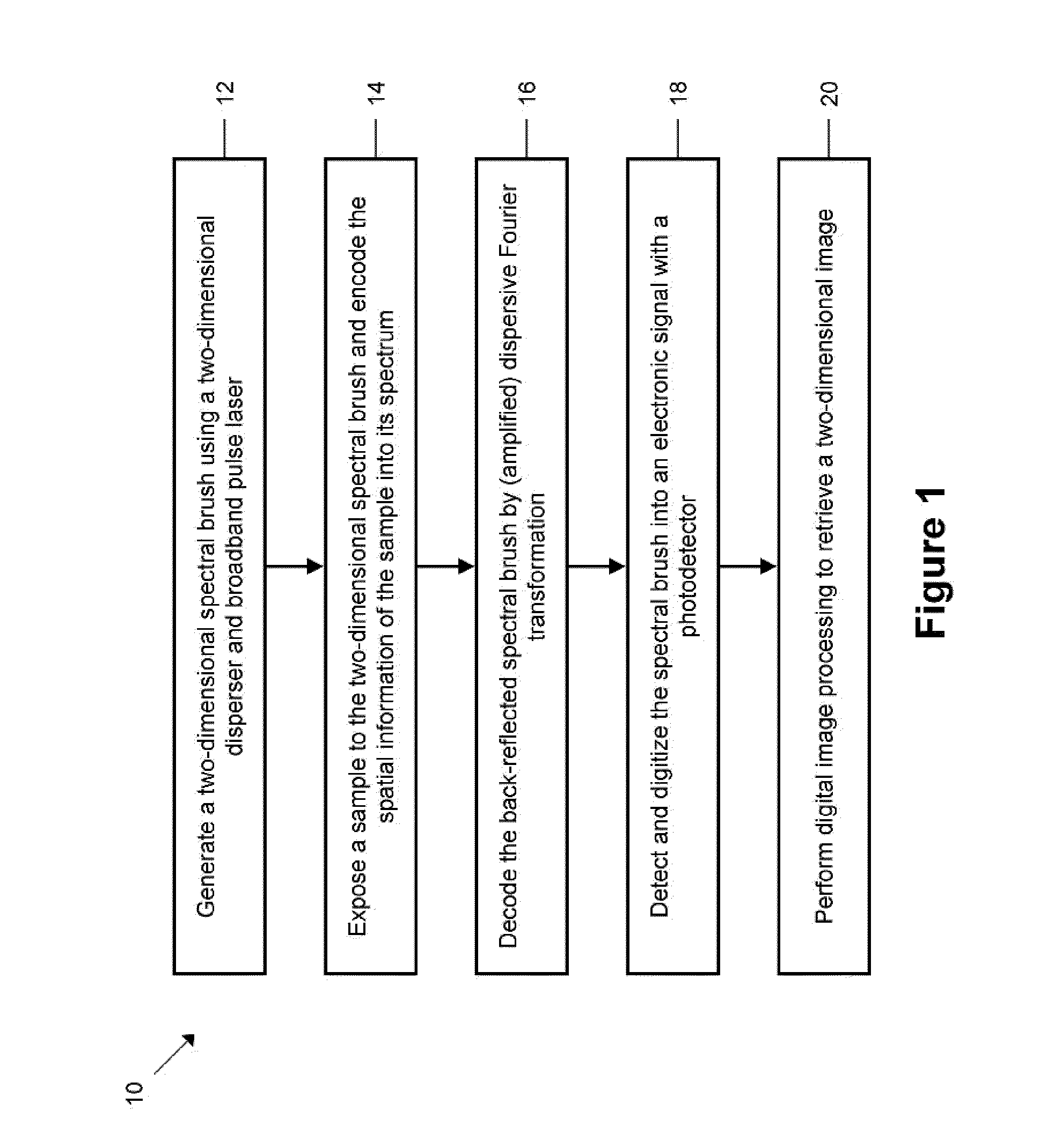
[0141]In order to demonstrate the functionality of the invention, the embodiment of the apparatus 116 shown schematically in FIG. 6 was constructed and tested using method shown in FIG. 1. The optical source that was used was a broadband pulse laser with a center wavelength and bandwidth of 1587 nm and 15 nm, respectively. The average optical power and pulse repetition rate of the laser was about 20 mW and 36.7 MHz, respectively. By pulse-picking the pulse train, the pulse repetition rate was reduced down to 6.1 MHz which is equivalent to a pulse interval of 163 ns. The spectrum of the laser was broadened by a high nonlinearity fiber to generate large bandwidth.

[0142]The combination of the virtually-imaged phased array (VIPA) with a free spectral range (FSR) of 67 GHz and a linewidth of 550 MHz and the diffraction grating with a groove density of 1200 lines / mm formed two-dimensional spectral brushes which are incident onto the sample. The average optical power of the spectral brush ...

example 2

[0149]A microfluidics experiment to attempt to observe ultrafast motion was conducted with the apparatus. In recent years, microfluidics has revolutionized molecular biology procedures for enzymatic analysis, proteomics, and DNA analysis based on polymerase chain reaction on microfluidic biochips.

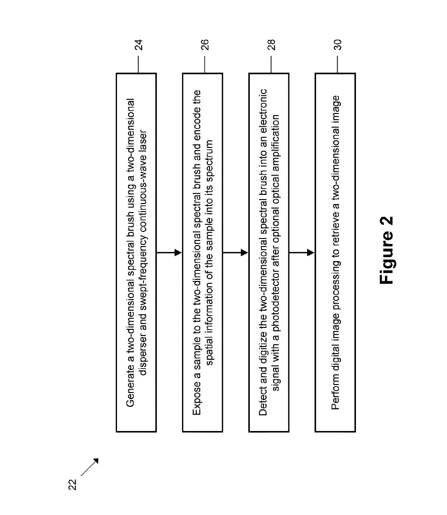
[0150]The optical source that was used was a mode-locked femtosecond laser. The center wavelength, bandwidth, pulse energy and pulse-repetition rate of the laser after spectral broadening, filtering and pulse picking were 1,590 nm, 15 nm, 82 pJ and 6.1 MHz, respectively. The 2D spectral pattern was produced by the 2D spatial disperser and focused onto the sample using an objective lens.

[0151]The 2D disperser was a pair of orthogonally oriented dispersers, which consisted of a diffraction grating with a groove density of 1,200 lines per millimeter and a virtually imaged phased array with a free spectral range of 67 GHz and a linewidth of 550 MHz. The amplified dispersive Fourier transformer ...

example 3

[0153]To show the nanosecond time-resolved real-time imaging capability of the invention, the dynamical process of a laser-induced surface change in combination with laser ablation was monitored with the imaging technique and the apparatus illustrated in FIG. 16. Laser ablation is a powerful tool that has been used for many applications including laser surgery, laser cutting, laser engraving, and laser-induced breakdown spectroscopy.

[0154]In this example, a mid-infrared excitation pulse laser (with a pulse energy of 6 mJ and a pulse width of 5 ns) was focused at an angle onto the sample with a bilayer of aluminum and silicon dioxide deposited on top of a silicon-on-insulator substrate, while the two-dimensional spectral brushes are normal and incident onto the surface of the sample. The excitation pulse for the laser ablation was an optical parametric oscillator pumped by a Nd:YAG Q-switched laser. It generates a high power pulse with a center wavelength of 2.8 μm. A lens with a foc...


PUM


Abstract

An apparatus and method for ultrafast real-time optical imaging that can be used for imaging dynamic events such as microfluidics or laser surgery is provided. The apparatus and methods encode spatial information from a sample into a back reflection of a two-dimensional spectral brush that is generated with a two-dimensional disperser and a light source that is mapped in to the time domain with a temporal disperser. The temporal waveform is preferably captured by an optical detector, converted to an electrical signal that is digitized and processed to provide two dimensional and three dimensional images. The produced signals can be optically or electronically amplified. Detection may be improved with correlation matching against a database in the time domain or the spatial domain. Embodiments for endoscopy, microscopy and simultaneous imaging and laser ablation with a single fiber are illustrated.

Description

CROSS-REFERENCE TO RELATED APPLICATIONS[0001]This application claims priority to U.S. provisional patent application Ser. No. 61 / 115,770 filed on Nov. 18, 2008, incorporated herein by reference in its entirety, and to U.S. provisional patent application Ser. No. 61 / 115,775 filed on Nov. 18, 2008, incorporated herein by reference in its entirety.STATEMENT REGARDING FEDERALLY SPONSORED RESEARCH OR DEVELOPMENT[0002]This invention was made with Government support of Grant No. H94003-07-2-0702, awarded by the U.S. Department of Defense, Defense Microelectronics Activity and of Grant No. N66001-07-1-2007 awarded by the U.S. Department of the Navy. The Government has certain rights in this invention.INCORPORATION-BY-REFERENCE OF MATERIAL SUBMITTED ON A COMPACT DISC[0003]Not ApplicableBACKGROUND OF THE INVENTION[0004]1. Field of the Invention[0005]This invention pertains generally to optical imaging devices and methods and more particularly to an apparatus and method for high-speed, real-ti...

Claims


Application Information

Patent Timeline
Patent Type & Authority Patents(United States)
IPC IPC(8): H01L27/00H01L31/00G06V10/145
CPCA61B1/00009G02B21/361A61B5/0062A61B5/0086G01B11/2441G06K9/2036H04N9/045G01B9/02004G01B9/02028G01B9/02044G01B9/02091G01B9/02014A61B1/00193A61B1/0638A61B5/0066A61B5/0075A61B5/7257G06K2209/05G01B2290/20G01B2290/65G06V10/145G06V2201/03
Inventor JALALI, BAHRAMGODA, KEISUKETSIA, KEVIN KIN-MAN
Owner RGT UNIV OF CALIFORNIA
Why Eureka
Try Eureka