
Solid oxide fuel cell composite electrolyte film and preparation thereof

A composite electrolyte and electrolyte film technology, applied in the field of solid oxide fuel cells, can solve the problems of easy occurrence of harmful chemical reactions, low oxygen ion conductivity, and large battery ohmic resistance, so as to improve long-term stability and reliability, improve The effect of high output performance and open circuit voltage

Active Publication Date: 2014-06-25
DALIAN INST OF CHEM PHYSICS CHINESE ACAD OF SCI
View PDF2 Cites 12 Cited by
  • Summary
  • Abstract
  • Description
  • Claims
  • Application Information

AI Technical Summary

Problems solved by technology

[0004] However, the most mature zirconia-based electrolyte membranes (such as Y 2 o 3 Stable ZrO 2 、Sc 2 o 3 Stable ZrO 2 ) has a low oxygen ion conductivity, resulting in a large ohmic resistance of the battery, and it is different from the currently used medium and low temperature high-performance cobalt-containing cathode materials, such as Ba x Sr 1-x co y Fe 1-y o 3 (BSCF) (0x Sr 1-x co y Fe 1-y o 3 (LSCF) (Ln=La, Sm, Nd, Gd, or Dy, 0x Sr 1-x CoO 3 (LSC) (0x Sr 1-x CoO 3 (SSC) (0<x<1), etc., have poor chemical compatibility, and harmful chemical reactions are prone to occur during the sintering and operation of the cathode, and high-resistance phase impurities are generated on the interface between the cathode and the electrolyte, causing the battery performance to decline sharply
[0005] Cerium oxide-based electrolyte films (such as Gd 2 o 3 Doped CeO 2 、Sm 2 o 3 Doped CeO 2 ) has high ionic conductivity, but it is easy to reduce with the fuel on the anode side during the operation of the battery to generate electronic conductivity, which reduces the performance of the battery, and more fatally, the reduction of cerium oxide can cause the rupture of the electrolyte film. Can completely make the battery scrapped

Method used


Image

  • Solid oxide fuel cell composite electrolyte film and preparation thereof
  • Solid oxide fuel cell composite electrolyte film and preparation thereof
  • Solid oxide fuel cell composite electrolyte film and preparation thereof

Examples


Embodiment 1

[0033] In nickel oxide with Y 2 o 3 Stable ZrO 2 Sputtering Dense Y on Composite Anode Substrate 2 o 3 Doped ZrO 2 (Y 0.08 Zr 0.92 o 2 ) Electrolyte film, after cleaning the anode substrate ultrasonically with acetone, ethanol, and distilled water and drying it, put it into the vacuum chamber of the magnetron sputtering instrument, adjust the target base distance to about 6cm, and use yttrium / zirconium alloy material as Target material, the purity of the target material is above 99.99%, the molar ratio of yttrium / zirconium is 8 / 92, and the vacuum is 8*10 -4 Pa, then turn on the substrate table to heat, the temperature rises to 400°C, the flow rate of argon gas is 10.0 sccm, the flow rate of oxygen is 1.0 sccm, and the sputtering power is 10W / cm 2 , the sputtering air pressure is 0.5Pa, the rotation speed of the substrate table is set at 5 cycles / min, and the thickness is about 1 μm. 0.08 Zr 0.92 o 2 After sputtering, anneal at 1200°C for 2 hours in the air atmospher...

Embodiment 2

[0036] In nickel oxide with Y 2 o 3 Stable ZrO 2 Sputtering Dense Y on Composite Anode Substrate 2 o 3 Doped ZrO 2 (Y 0.08 Zr 0.92 o 2 ) Electrolyte film, after cleaning the anode substrate ultrasonically with acetone, ethanol, and distilled water and drying it, put it into the vacuum chamber of the magnetron sputtering instrument, adjust the target base distance to about 7cm, and use yttrium / zirconium alloy material as Target material, the purity of the target material is above 99.99%, the molar ratio of yttrium / zirconium is 8 / 92, and the vacuum is 8*10 -4 Pa, then turn on the substrate table to heat, the temperature rises to 800°C, the flow ratio of oxygen and argon is 1 / 5, and the sputtering power is 12W / cm 2 , the sputtering pressure is 0.3Pa, the rotation speed of the substrate table is set to 8 cycles / min, the thickness is about 0.8μm, and the dense Y 0.08 Zr 0.92 o 2 After sputtering, replace the yttrium / zirconium alloy target with a cerium / samarium alloy tar...

Embodiment 3

[0039] In nickel oxide with Y 2 o 3 Stable ZrO 2 Sputtering Dense 10mol%Sc on Composite Anode Substrate 2 o 3 with 1mol%CeO 2 Co-doped ZrO 2 (Ce 0.01 sc 0.1 Zr 0.89 o 2 ) Electrolyte film, after cleaning the anode substrate ultrasonically with acetone, ethanol, and distilled water and drying it, put it into the vacuum chamber of the magnetron sputtering instrument, adjust the target base distance to about 7cm, use scandium / cerium / zirconium alloy The material is a target, the purity of the target is above 99.99%, the molar ratio of scandium / cerium / zirconium is 10 / 1 / 89, and the vacuum is 8*10 -4 Pa, then turn on the substrate table to heat, the temperature rises to 600°C, the flow ratio of oxygen and argon is 1 / 8, and the sputtering power is 9W / cm 2 , the sputtering pressure is 0.5Pa, the rotation speed of the substrate stage is set to 6 cycles / min, the thickness is about 0.8μm, and the dense Ce 0.01 sc 0.1 Zr 0.89 o 2 After the sputtering of , replace the Ce / Gd (9...


PUM

PropertyMeasurementUnit
thicknessaaaaaaaaaa
thicknessaaaaaaaaaa
thicknessaaaaaaaaaa

Abstract

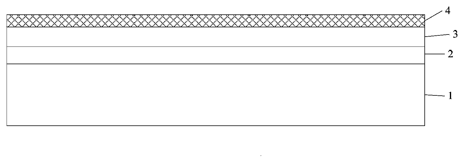
The invention discloses a solid oxide fuel cell composite electrolyte film containing a zirconia based electrolyte film and a ceria based electrolyte film, wherein the zirconia based electrolyte film is deposited on an anode substrate, and can effectively isolate the electronic conductivity, the ceria based electrolyte film is deposited on the zirconia based electrolyte film, can effectively isolate chemical reaction of a cathode and the zirconia based electrolyte film and element diffusion, and can improve the contact properties of a cathode / electrolyte interface; the composite electrolyte films are prepared by a magnetron sputtering method, reaction of zirconia and ceria based electrolytes can be avoided, and by use of the composite electrolyte film, diffusion of gases at both sides of the electrolytes can be effectively isolated, the ohmic resistance is reduced, and the cell performance is improved.

Description

technical field [0001] The invention relates to the field of solid oxide fuel cells, in particular to a composite electrolyte film on an electrode substrate and a preparation method thereof. Background technique [0002] Solid oxide fuel cell is an energy conversion device that can efficiently convert the chemical energy in fuel gas (such as hydrogen, natural gas, coal gas, etc.) Noise, is an ideal distributed power station and centralized power station technology, and can also be applied to vehicle auxiliary power supply, portable power supply, etc. [0003] In order to reduce manufacturing costs, improve long-term battery stability and reliability, shorten start-up time, and meet commercial application requirements, reducing the operating temperature of solid oxide fuel cells has become the focus of research and development at home and abroad. There are two main ways to reduce the operating temperature of the battery. One is to use highly active electrode materials, such ...

Claims


Application Information

Patent Timeline
Patent Type & Authority Applications(China)
IPC IPC(8): H01M8/10H01M8/02
CPCH01M8/1253H01M8/126H01M2008/1293Y02E60/50
Inventor 程谟杰武卫明涂宝峰区定容崔大安
Owner DALIAN INST OF CHEM PHYSICS CHINESE ACAD OF SCI
Learn More