Method for biomass carbonization instead of pulverized coal injection in blast furnace

A technology of biomass charcoal and pulverized coal injection, applied in blast furnaces, biofuels, blast furnace details, etc., can solve problems such as the lack of high-quality coal resources and the difficulty of using poor coal resources, so as to reduce the amount of flux and reduce the amount of blast furnace slag , the effect of saving resources

Inactive Publication Date: 2018-05-08
UNIV OF SCI & TECH BEIJING
View PDF1 Cites 16 Cited by
  • Summary
  • Abstract
  • Description
  • Claims
  • Application Information

AI Technical Summary

Problems solved by technology

However, due to year-by-year mining, high-quality coal resources across the country are increasingly s

Method used


Image

  • Method for biomass carbonization instead of pulverized coal injection in blast furnace
  • Method for biomass carbonization instead of pulverized coal injection in blast furnace
  • Method for biomass carbonization instead of pulverized coal injection in blast furnace

Examples


Embodiment 1

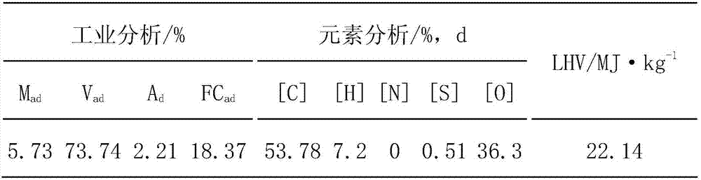
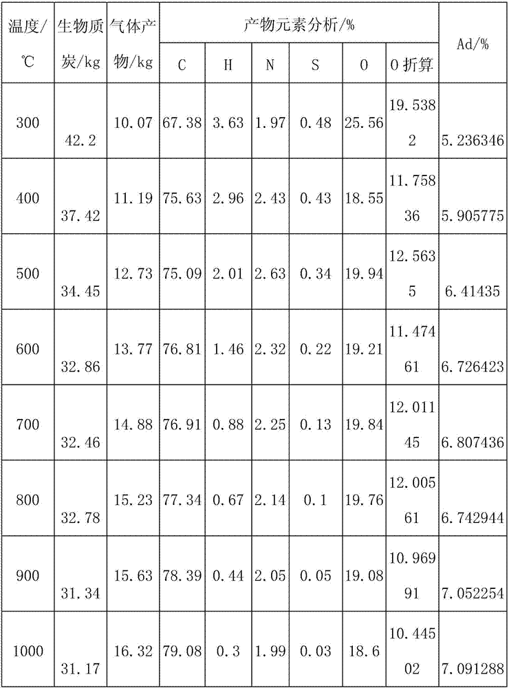
[0030] The industrial analysis and elemental analysis of a kind of straw are shown in attached table 1, and the analysis of pyrolysis products at different temperatures of 100kg is shown in attached table 2.

[0031] Schedule 1:

[0032]

[0033] Schedule 2:

[0034]

[0035] Take carbonization pyrolysis at 600°C as an example:

[0036] Among them, the content analysis of product biomass carbon element: 76.81% [C], 1.46% [H], 2.32% [N], 0.22% [S], 19.21% [O], 11.47% [O] converted, 6.73% ash.

[0037] Gas product analysis (mass fraction): 11.42% CH 4 , 42.36%CO 2 , 25.12%H 2 , 21.1% CO, n 总 is 0.51, and the specific heat capacity of the mixed gas is 286711.1kJ / kg (gas product molar conversion: 0.058511CH 4 , 0.217033CO 2 , 0.128703H 2 , 0.108106CO)

[0038]From attached table 1 and attached table 2, it can be seen that every 100kg of straw can produce about 35kg of biomass charcoal, its carbon content is more than 75%, and its ash content is about 6%, while t...

Embodiment 2

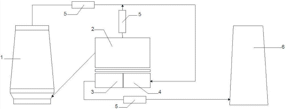
[0040] Such as figure 1 As shown, the process flow diagram of the method of biomass carbonization instead of pulverized coal injection in the blast furnace of the present invention, firstly, the straw is screened by a screening machine to remove impurities, and then the straw is dried to a moisture content lower than 7% by a dryer. Under the conditions of 250-300° C., pressure of 78 MPa, and humidity of less than 7%, the straw is subjected to biomass extrusion molding. Carbonize the machine-made rods obtained by extruding in an external heating carbonization furnace to obtain biomass charcoal and flue gas. The carbonization temperature is 300-1000°C, the charcoal yield exceeds 30%, the fixed carbon content reaches about 80%, and the ash content is about The carbon yield, fixed carbon content and ash content vary with the type of biomass and pyrolysis temperature. The externally heated carbonization furnace uses blast furnace gas and carbonization furnace flue gas to burn and ...


PUM


Abstract

The invention provides a method for biomass carbonization instead of pulverized coal injection in a blast furnace. Dried straw and other biomass raw materials are extruded to obtain a machine-made rod, and the machine-made rod is carbonized by a carbonization furnace to obtain carbon powder at a temperature of 300 to 1000 DEG C. The carbon powder obtained by the furnace is mixed with pulverized coal and injected into the blast furnace to greatly reduce a coal ratio and flux usage amount and improve production efficiency; latent heat of flue gas is fully utilized to reduce emission of exhaust gas; the exhaust gas discharged from a combustion chamber is filtered and discharged into air through a microporous ceramic tube. Biomass resources and sensible heat of the flue gas, and oxygen and carbon monoxide in the flue gas are used in ironmaking production. In addition, the biomass resources can also be used as a substitute for the pulverized coal or coke powder used in iron ore sintering machines. The method comprehensively utilizes existing equipment to treat waste materials such as biomass raw materials and the flue gas, saves coking coal resources, fully exerts potential advantages of biomass energy, protects environment, and reduces costs.

Description

technical field [0001] The invention belongs to the technical field of biomass carbonization and metallurgy, and in particular relates to a method for biomass carbonization instead of pulverized coal injection into a blast furnace. Background technique [0002] Coke is a precious non-renewable resource, which is formed by dry distillation of coal at high temperature (900-1000°C). It provides most of the heat for blast furnace smelting and at the same time provides the reducing agent required for the smelting process, and constitutes the blast furnace charge column The skeleton plays an irreplaceable role. As the global coking coal resources are decreasing day by day, the price of coke is rising year by year. Major steel mills in the world generally adopt means such as blast furnace injection fuel to reduce the coke ratio and save costs. However, due to year-by-year mining, high-quality coal resources across the country are increasingly scarce, and the difficulty of using po...

Claims


Application Information

Patent Timeline
IPC IPC(8): C10L5/44C10L5/04C10L10/02C10B53/02C21B5/00
CPCC10B53/02C10L5/04C10L5/447C10L10/02C10L2270/00C10L2290/02C21B5/00Y02E50/10Y02E50/30
Inventor 焦楷袁章福谢珊珊王容岳刘建华
Owner UNIV OF SCI & TECH BEIJING
Why Eureka
Try Eureka