Electrocatalytic coupling advanced oxidation system

A technology of advanced oxidation and electrocatalysis, applied in the fields of oxidizing water/sewage treatment, chemical instruments and methods, water/sludge/sewage treatment, etc., can solve problems such as pollution, achieve good experimental repeatability, easy recovery, and cheap materials easy-to-get effect

Active Publication Date: 2018-05-15
NANCHANG HANGKONG UNIVERSITY
View PDF6 Cites 8 Cited by
  • Summary
  • Abstract
  • Description
  • Claims
  • Application Information

AI Technical Summary

Problems solved by technology

[0004] The purpose of the present invention is to provide an electrocatalytic coupled advanced oxidation system, specifically related to a novel coupled electrocatalytic method and a preparation scheme for a new electrode material, which provides new ideas and new materials for solving current pollution and energy problems

Method used


Image

  • Electrocatalytic coupling advanced oxidation system
  • Electrocatalytic coupling advanced oxidation system
  • Electrocatalytic coupling advanced oxidation system

Examples


Embodiment 1

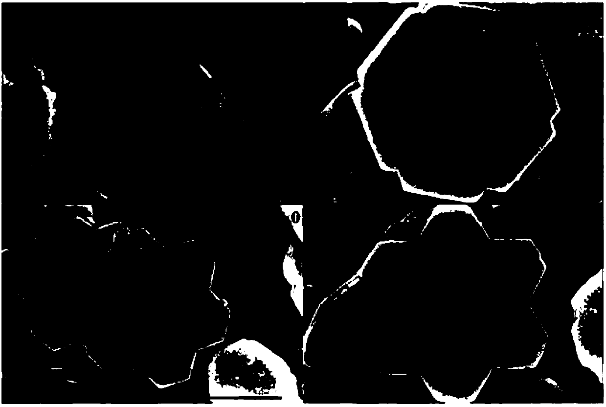
[0032] Three-dimensional six-pointed star-shaped Co 3 o 4 Synthesis of Electrode Anode Materials:

[0033] Dissolve 2 mmoles of 0.582 grams of cobalt nitrate in 10 milliliters of ethylene glycol and 30 milliliters of water and stir. After completely dissolving, add 0.5 grams of urea and stir evenly, then add 0.05 grams of cetyltrimethylammonium bromide and 1.455 grams of fluoride ammonium, stirred at 25°C for 30 minutes to form a homogeneous, transparent, colorless solution, and the solution was transferred to a 100 ml polytetrafluoroethylene reactor lining. Then place a piece of cleaned conductive glass (1.5 cm × 4.0 cm) in the reaction kettle at an angle, with the conductive side of the conductive glass facing up, and finally transfer the reaction kettle to a drying oven at 120°C for reaction, and react for 12 hours to obtain a purple color on the conductive glass. precursors. Put its conductive glass into a muffle furnace, pre-calcined at 350°C for 2 hours, then calcined...

Embodiment 2

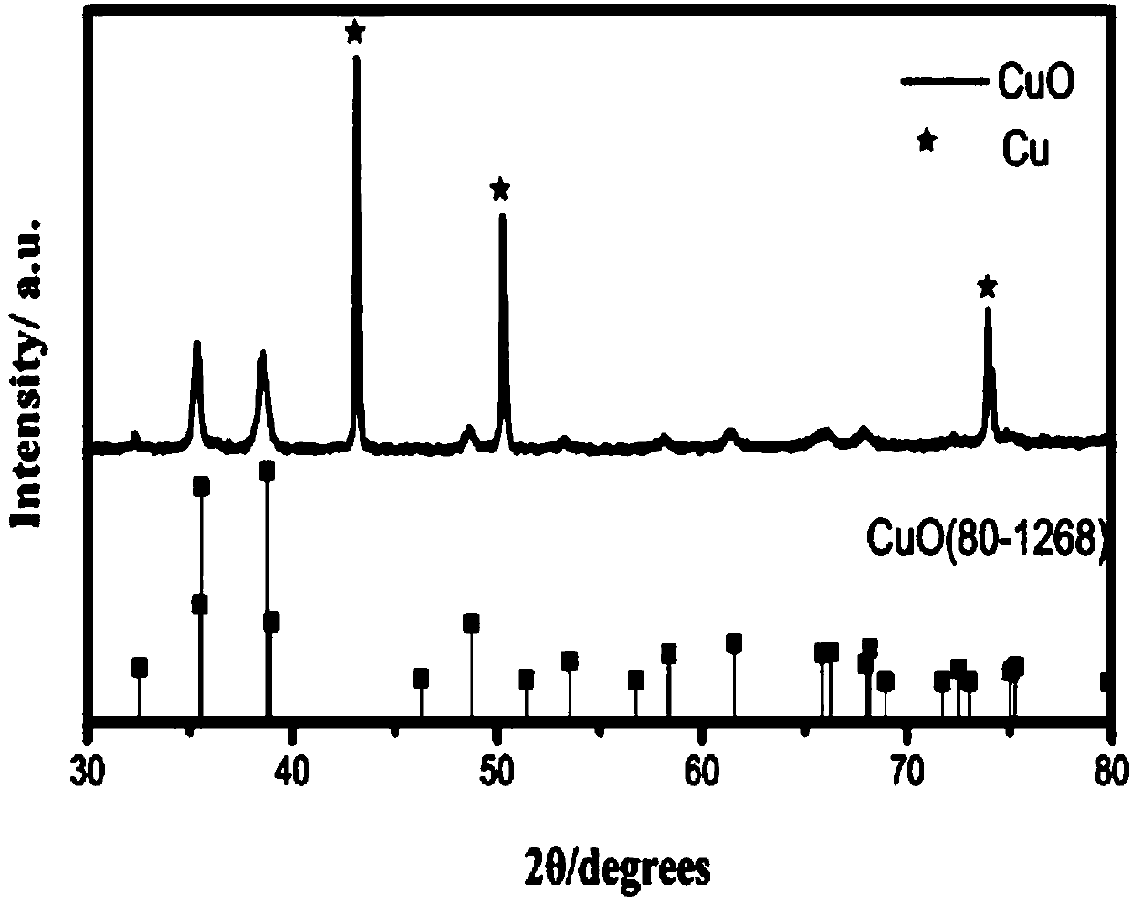
[0035] Synthesis of nanosheet-stacked flower-like CuO cathode: 6.4g of sodium hydroxide, 1.0954g of ammonium persulfate and 0.211g of sodium tungstate were dissolved in 32ml of deionized water and stirred at 25°C for 30 minutes to form a uniform, transparent, colorless solution. Then 0.4614 g of sodium lauryl sulfate was added to the above solution to form a uniform white solution. After the sodium lauryl sulfate is completely dissolved, move it into a polytetrafluoroethylene-lined stainless steel autoclave, and immerse the cleaned copper mesh (1.5 cm × 4.0 cm) in the above solution. The autoclave was closed and reacted at 130°C for 24 hours, then cooled to room temperature, the copper grid was taken out, and washed with deionized water to obtain a black sample CuO.

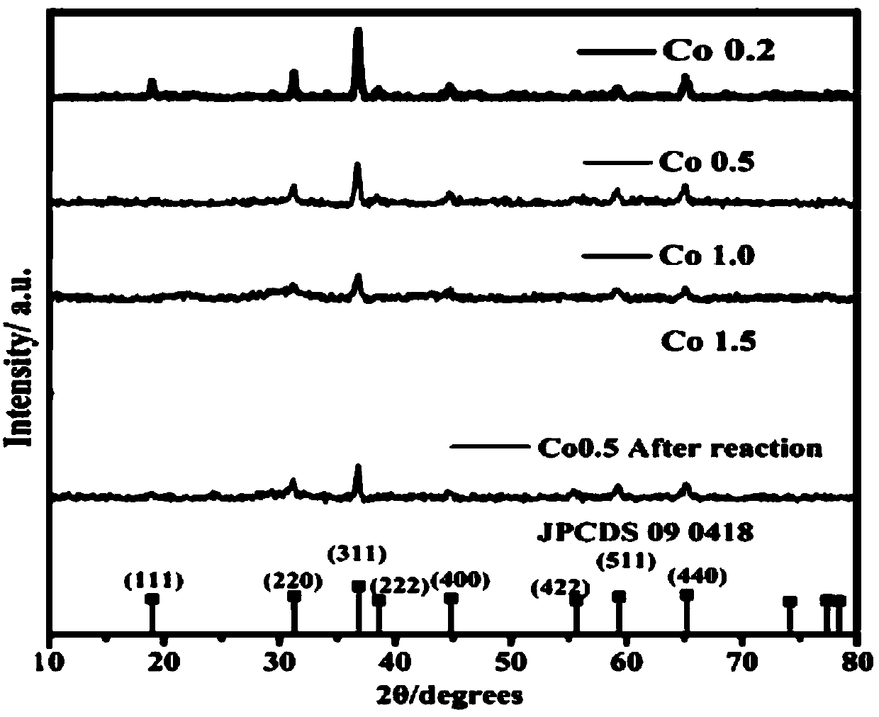
[0036] Such as Figure 1-Figure 8 As shown, the X-ray powder diffraction test results show that:

[0037] The diffractograms of a series of Co0.2, Co0.5, Co, 1.0 and Co1.5 catalysts of the present invention an...

Embodiment 3

[0040] In a conventional H-type electrolytic cell reaction system, the three-dimensional six-pointed star-shaped Co 3 o 4 CuO and nanosheet stacked flower-like CuO were used as anode and cathode materials respectively, and a 0.1 mol / L sodium sulfate solution (60 ml in volume) was added to the anode compartment, and a 0.1 mol / L potassium bicarbonate solution (60 ml in volume) was added to the cathode compartment. , and then add 0.5 g / L persulfate and 10 mg / L p-nitrophenol solution to the anolyte, and electrify to carry out electrolysis and advanced oxidation coupling reaction.

[0041] When the applied bias is -0.8V vs Ag / AgCl, Co 3 o 4 The removal rate of p-nitrophenol at the electric anode can reach more than 98%, and the CuO electric cathode can simultaneously reduce carbon dioxide to methanol and ethanol with yields of 49.145 and 20.475 micromoles / liter / hour, respectively. The Co of the present invention can be confirmed by the full-band degradation data 0.5 Catalyst ca...


PUM


Abstract

The invention provides an electrocatalytic coupling advanced oxidation system. The system can degrade organic pollutants into carbon dioxide and the carbon dioxide is synchronously electrocatalytically reduced to a hydrocarbon. In the catalytic system, three-dimensional hexagram-shaped Co3O4 and nano-sheet stack flower-shaped CuO are respectively used as an anode material and a cathode material, and the two electrode materials are prepared by a solvothermal method. In the three-electrode system electro-catalytic process, the Co3O4 electro-anode can thoroughly mineralize p-nitrophenol to CO2 and H2O, and the CuO electro-cathode can synchronously reduce the generated carbon dioxide into the useful hydrocarbon. When the additionally-applied bias voltage is 0.8V vs Ag/AgCl, the material has anoptimal catalytic effect, the removal rate of the p-nitrophenol can reach 98% or more, and the yields of methanol and ethanol reach 49.145 micromol/L/h and 20.475 micromol/L/h, respectively.

Description

technical field [0001] The invention relates to an electrocatalytic coupling advanced oxidation system, which belongs to the field of sewage treatment. Background technique [0002] The rapid development of industrialization and urbanization has brought highly developed material civilization to mankind, but it has also brought serious problems such as environmental pollution and resource shortage that cannot be ignored. Continuously increasing pollution will not only cause serious problems like global warming, but also threaten our life. Among them, a large amount of industrial wastewater is discharged and a large amount of CO is produced after the combustion of fossil energy. 2 particularly attracting attention. At present, water environmental pollutants are not only simple inorganic pollutants, but also more and more complex components, and the problem of organic pollution with higher and higher concentrations is becoming more and more serious. How to deal with these hi...

Claims


Application Information

Patent Timeline
Patent Type & Authority Applications(China)
IPC IPC(8): C02F1/461C02F1/72C02F101/34C02F101/38
CPCC02F1/46109C02F1/4672C02F2001/46142C02F2101/345C02F2101/38
Inventor 董文华邢秋菊刘闪闪邹建平陈颖朱蒙罗胜联李佩杨景心
Owner NANCHANG HANGKONG UNIVERSITY
Why Eureka
Try Eureka