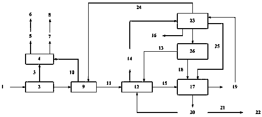
Recycling treatment method and apparatus for oil-containing sludge

A resource-based, oil-water separation device technology, which is applied in the field of oily sludge treatment, can solve the problems of relatively harsh treatment scale process conditions, the influence and limitation of mixed bacterial agent biological treatment, and insufficient energy utilization of pyrolysis oil and gas, etc., to achieve the realization of Acceleration and strengthening effect, improving the effect of plasma gasification, reducing the effect of electric power

Active Publication Date: 2018-07-27
CHINA PETROLEUM & CHEM CORP +1
View PDF7 Cites 15 Cited by
  • Summary
  • Abstract
  • Description
  • Claims
  • Application Information

AI Technical Summary

Problems solved by technology

[0005] CN 103626366 A discloses a treatment method for recycling oily sludge in oilfields. The method uses a water-assisted solvent to extract and separate the oily sludge, and the phase separation effect is better, but the subsequent sludge adopts a biological treatment method of mixed microbial agents , the treatment effect is unstable, and the biological treatment of mixed bacterial agents is easily affected and limited by many conditions
[0006] CN 105314812 A discloses a sludge treatment system and its treatment method. In the method, a drying device and a pyrolysis furnace are used to pyrolyze sludge. The system has a simple structure and low energy consumption, but only burns pyrolysis oil gas Heat exchange, pyrolysis of oil and gas energy utilization is insufficient, at the same time

Method used


Image

  • Recycling treatment method and apparatus for oil-containing sludge

Examples


Embodiment 1

[0045] (1) The oily sludge with a moisture content of 96wt% or more is dehydrated by the screw stacker and the air flotation device, and the small particle oily sludge is flocculated and precipitated by adding polyacrylamide flocculant, and dehydrated by the screw stacker The treatment reduces the water content to 80wt%~90wt%. The sewage generated during the dehydration process of the screw stacker is sent to the air flotation machine for secondary dehydration treatment. The generated scum is returned to the screw stacker, and the generated sewage is sent to the oil-water separation device;

[0046] (2) The dehydrated oily sludge with a moisture content of 80wt%~90wt% is transported to the multi-layer film evaporation and drying device through the sludge screw pump for drying treatment, and the dehydrated oily sludge is dried with saturated steam at 160~180°C Drying and purging, the drying temperature of the inner layer of the film can reach 120-140°C, and the purging temperat...


PUM


Abstract

The invention discloses recycling treatment method and apparatus for oil-containing sludge. The method includes steps of: 1) performing dehydration to the oil-containing sludge to separate an oil/water mixture, feeding the oil/water mixture to an oil-water separator to separate the water phase and the oil phase; 2) drying the dehydrated oil-containing sludge to discharge water and oil vapor, thusforming solid oil sludge; 3) sending the discharged water and oil vapor to the oil-water separator; 4) pyrolyzing the dried solid oil sludge to form pyrolysis gas, pyrolysis oil and pyrolysis charcoal; 5) performing plasma gasification to the pyrolysis charcoal to form synthetic gas and vitreous body slag; 6) performing heat exchange to the pyrolysis gas obtained in the step 4) and the synthetic gas in the step 5) and feeding the gas to a fuel power generation apparatus; 7) sending one part of the vitreous body slag, obtained in the step 5), to a pyrolysis furnace as a heat source, and coolingthe other part to room temperature to obtain a building material. The method can convert the oil-containing sludge into the vitreous body slag and synthetic gas without secondary pollution, thus achieving harmless treatment of the oil-containing sludge.

Description

technical field [0001] The invention belongs to the technical field of oily sludge treatment, and in particular relates to a method and device for resourceful treatment of oily sludge, which can realize the reduction, resourceful and harmless treatment of oily sludge. Background technique [0002] In the process of oil extraction, storage, transportation, oil refining, cleaning and refinery wastewater treatment, a large amount of oily sludge is often produced, which is mainly composed of water, oil, and mud-like solids. The composition of oil sludge is relatively complex, generally containing a certain amount of crude oil (generally 5wt%~20wt%), heavy metal ions (iron, copper, chromium, zinc, nickel, etc.) and inorganic compounds (mainly in the form of inorganic salts). At the same time, Due to the difference in crude oil quality, refining process and method, the composition of oily sludge is not fixed. In oily sludge, the common organic substances are mainly benzene series...

Claims


Application Information

Patent Timeline
IPC IPC(8): C02F11/10C02F11/12C02F11/14C10B49/02C10B53/00C10J3/20C02F101/20C02F101/30
CPCC02F11/10C02F11/121C02F11/14C02F2101/20C02F2101/30C10B49/02C10B53/00C10J3/20C10J2300/0923Y02W10/40
Inventor 冯文龙回军吴巍李宝忠
Owner CHINA PETROLEUM & CHEM CORP
Why Eureka
Try Eureka