Self-cohering, continuous filament non-woven webs

a non-woven web and continuous filament technology, applied in the field of self-cohering, continuous filament non-woven webs, can solve the problems of increasing the potential for colonization and wicking of bacteria within the interstices of aligned fiber bundles, high cost and complexity of knitting and weaving equipment, and few fibrous implants that utilize non-woven constructions

Inactive Publication Date: 2001-04-19
WL GORE & ASSOC INC
View PDF0 Cites 18 Cited by
  • Summary
  • Abstract
  • Description
  • Claims
  • Application Information

AI Technical Summary

Benefits of technology

156. Additionally, bonding of similarly quenched and preserved substantially amorphous objects may again be achieved by raising the temperature of the objects to be joined above the homogenous single but separable phased system's

Problems solved by technology

Besides the high cost and complexity of the knitting and weaving equipment, a particular additional drawback of such construction is an increased potential for colonization and wicking of bacteria within the interstices of the aligned fiber bundles if the implant becomes contaminated.
However, few fibrous implants utilize non-woven constructions since the mechanical interlocking between fibers in such webs are generally weak.
Consequently only limited applications such as felts and pledgets exist for the non-woven implantables that are dependent on fiber entanglement for their mechanical integrity; these possess relatively poor cohesive or tensile strength.
It is not bioresorbable, however, and must be removed in a subsequent surgical procedure.
Reproductions of this material demonstrated poor surgical handling characteristics due to its thin friable construction and also proved to be difficult to suture because of its brittleness.
As these are somewhat contradictory objectives for a single layer material of woven construction having a degree of inherent porosity, ingrowth can only be made to occur at the expense of the barrier function.
An additional difficulty with this conventional woven construction is its lack of adequate rigidity and a resulting inferior ability to maintain space adjacent to the defect.
In such applications open celled bioresorbable foams are common, however these materials generally possess limited tensile strength since it is relatively difficult to introduce molecular alignment, also known as molecular orientation, into such a structure.
However, three dimensional fibrous webs cannot be readily produced without the use of either adhesives, adhesive adjuncts, or compression, two of which are processes which inherently reduces the loft of the web leading to more web density and a consequential reduction in the potential for tissue integration.
Besides introducing an ongoing risk of dissimilar degradation profiles, the use of an additional adhesive to bond between the web's filaments leads to more material present within the web resulting in decreased void space and an increased mass that delivers the expectation of a proportionally more reactive tissue response upon bioresorption.
However, since heating fibers in the solid state can deliver only limited melt viscosity to the bonding interface without damaging overall fiber integrity, such an approach commonly delivers relatively weak inter-fiber attachments when compared with webs utilizing adhesive binders.
Also, regardless to the quality of the produced inter-fiber bonds, such compression under heat inherently reduces web loft, therefore increasing the web's apparent or overall density and limiting the relative amount of available open space within the web for tissue ingrowth.
However, current non-woven fabrics, especially those constructed from bioresorbable polymers, do not meet this need.
Fibers in web form are typically bonded together at their points of contact by the application of various known binders or binding techniques, many of which also include the application of pressure which in turn reduces the available loft.
The use of any external binder also introduces issues of the u

Method used


Image

  • Self-cohering, continuous filament non-woven webs
  • Self-cohering, continuous filament non-woven webs
  • Self-cohering, continuous filament non-woven webs

Examples


example 1-- preparation

Example 1--Preparation of Web

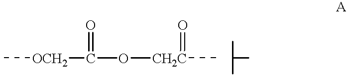
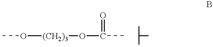
164. 67% poly(glycolide) 33% poly(trimethylenecarbonate) (w / w) triblock copolymer was acquired from Davis & Geck (Danbury, Conn.)-Lot #10-CV-9433. This bioresorbable copolymer is commonly referred to by Davis & Geck as polyglyconate.

165. Approximately 25 mg of the acquired copolymer was dissolved in 25 ml of hexafluoroisopropanol (HFIP). The produced dilute solution was found to possess an inherent viscosity (IV) of 1.53 dl / g when measured using a Cannon-Ubelodde viscometer immersed in a 30.degree. C. (+ / -0.05.degree. C.) water bath.

166. Approximately 10 mg of the acquired copolymer was placed into an aluminum DSC sample pan, covered, and analyzed utilizing a Perkin-Elmer DSC 7 equipped with an Intracooler II cooling unit able to provide sample cooling to temperatures as low as -40.degree. C. After preconditioning of the sample at 180.degree. C. for 2 minutes, the sample was cooled at the maximum rate provided by the instrument (-500.degree. C. / min setti...

example 2--

Characterization of Example 1 Web

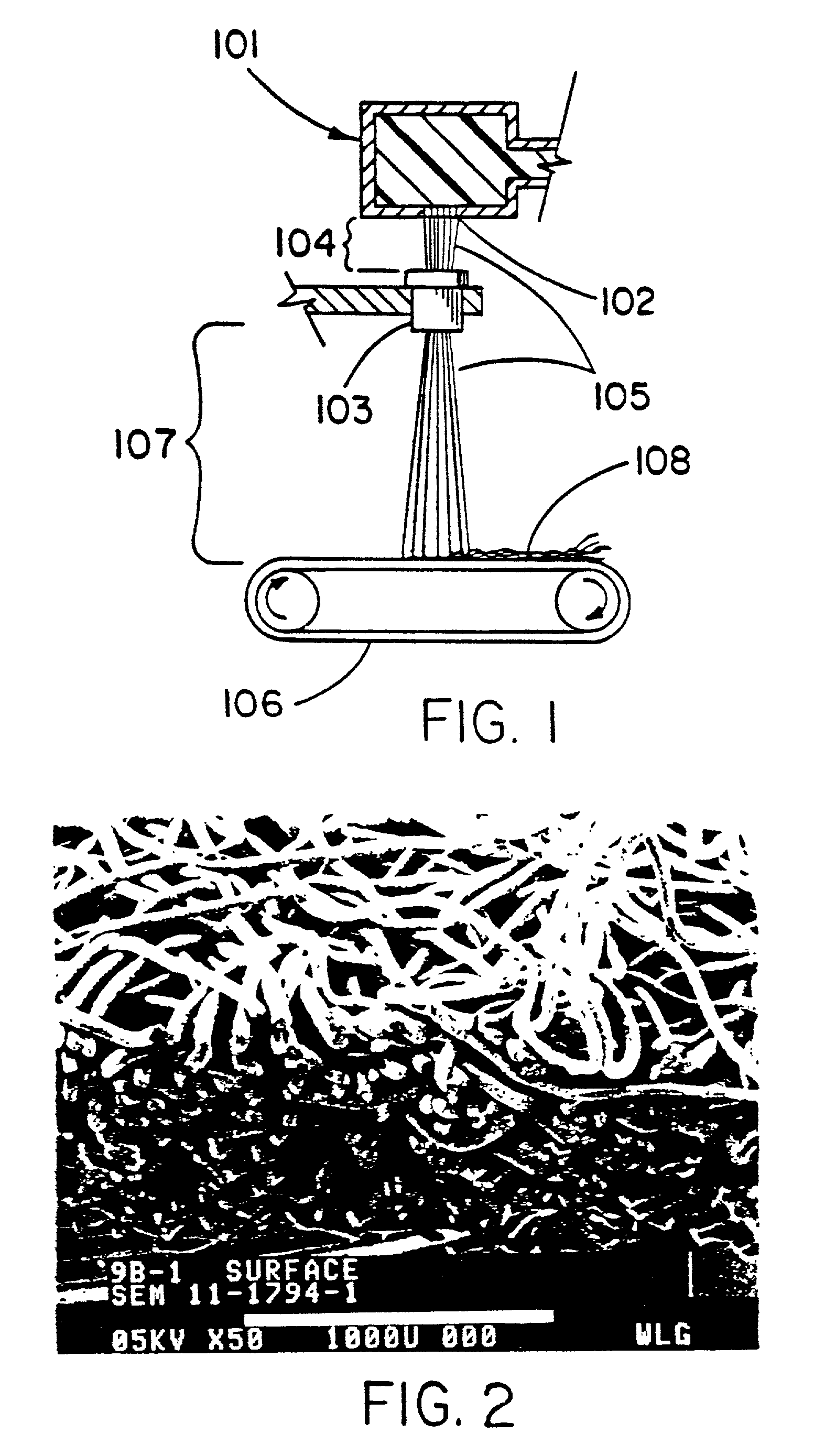
172. Filament Diameter

173. A sample of the cohesive web produced in Example 1 was observed utilizing both light microscopy and scanning electron microscopy (SEM) at magnifications between 20.times. and 1000.times. (see FIG. 2 for example). The examined web was found to be composed of fibers ranging in diameter from approximately 20 to 100 micrometers.

174. Web Bonding Characteristics

175. Further examination of the contact points between fibers utilizing both light microscopy and SEM at 1000.times. showed the web's fibers to physically intersect with each other with limited distortion or deformation of the contacting fibers' cylindrical form or nature. This observed physical intersection and interfiber contact was assumed to be autogenous self-cohesion since no adhesive binders or adjuncts had been added to the copolymer either before, during, or after the extrusion process described in Example 1.

176. No Noticeable Fraying

177. Visual examination also r...

example 3--

Shaping (Molding) of Web in 37.degree. C. Water

193. Arch Form

194. After over 24 months continuous storage under refrigerated conditions, a 2.5 cm.times.2.5 cm section was obtained from the web described in Example 1 and characterized in Example 2. The section of web was formed into an arch and restrained so that the outside edges of the arch were separated by approximately a 0.7 cm distance. This distance is intended to approximate the width of a mandibular ridge. The web section was then immersed into a 37.degree. C. water bath while maintaining its restrained arched configuration. After 10 minutes of 37.degree. C. immersion, the piece was removed from both the bath and its restraint and allowed to return to room temperature. The web was found to have retained its arched configuration upon removal.

195. The preformed arched web was then restrained so that the separation between the outer opposite edges was approximately 2.0 cm apart. The restrained web was then reimmersed into the 3...


PUM

PropertyMeasurementUnit
Shear strengthaaaaaaaaaa

Abstract

A web of continuous filaments which are made of at least one semi-crystalline polymeric component covalently bonded as a linear block copolymer with or blended with one or more semi-crystalline or amorphous polymeric components. The filaments are intermingled together to form a porous web of filaments, the filaments having multiple contact points with each other within the web. The filaments are bonded at the contact points without requisite for added adhesive binders, adjuncts or post extrusion melt processing. The web may be bioresorbable. The web may also be provided in forms with relatively high cohesive shear strength. The polymeric components of the filaments exist, at least temporarily, in a homogenous substantially phase miscible uncrystallized state. If preserved in the homogenous substantially phase miscible uncrystallized state, the object can then be manipulated into a distinct desirable molded shape and then subsequently set or crystallized to retain the desired form particularly suitable for a specific use or application.

Description

1. This application is a division of application Ser. No. 08 / 942,371 filed Oct. 2, 1997.2. This invention relates to continuous filament non-woven structures fabricated from semi-crystalline polymeric materials. More particularly the invention relates to said structures that are self-cohering webs fabricated from bioresorbable polymeric materials which are found useful as surgical implants.3. This invention relates to compositions that are useful in medical applications intended to provide for integration with and subsequent attachment to the surrounding mammalian tissue. A requirement for any medical device that is to become well integrated with the surrounding host tissue is an open structure on the surface of the implant that is sufficiently large for cells to readily penetrate. If the open structure is sufficiently large to allow for the ingrowth of both collagenous and vascular tissues, a well tolerated attachment between the implant and the surrounding tissue is then possible....

Claims


Application Information

Patent Timeline
IPC IPC(8): A61L31/06A61L27/00A61L31/14D04H3/03D04H3/14D04H3/16
CPCA61L31/06A61L31/14D01D5/0985D01F6/84D04H3/03D04H3/14D04H3/163C08L67/04Y10T428/1372Y10T428/1376D04H3/011D04H3/077Y10T428/249928
Inventor HAYES, BYRON K.
Owner WL GORE & ASSOC INC
Why Eureka
Try Eureka