Unfortunately, the reactors and plants are extremely complex.
The stirred polycondensation reactors have complex designs, which require detailed calculations and craftsmanship.
These complex designs cannot be built or installed quickly.
These reactors normally have scrapers or other highly complicated devices for keeping the vapor lines from plugging.
These cylindrical reactors require a large amount of
engineering, drafting, and skilled craftsmanship to construct.
The extra complexity, materials, and skill required to construct the cylindrical reactors leads to the higher cost.
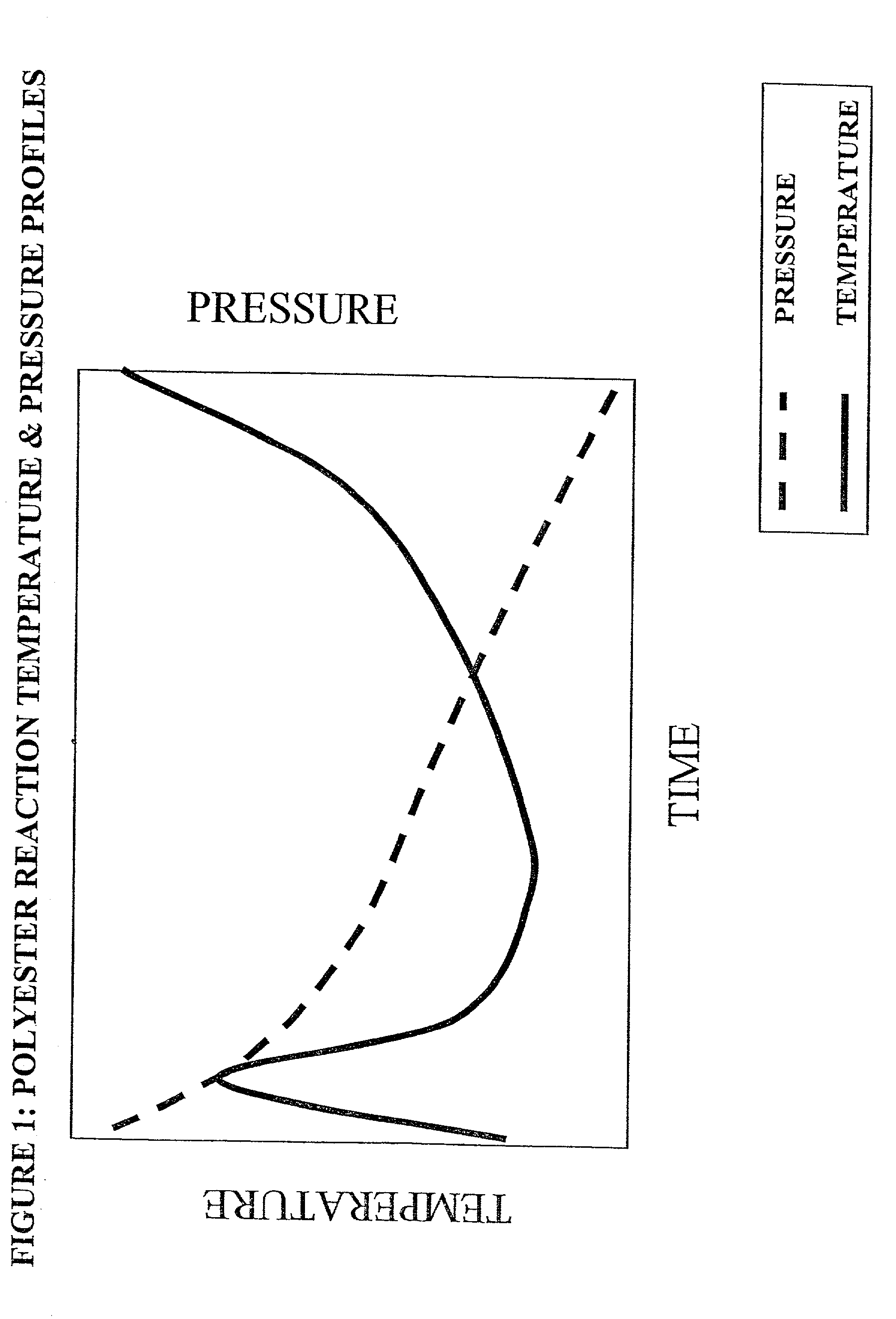
While it has been theorized that optimum ester exchange or esterification would occur in a continuum of continuous
pressure reduction and continuous temperature increase (see FIG. 1, Santosh K. Gupta and Anil Kumar, Reaction
Engineering of
Step Growth Polymerization, The Plenum
Chemical Engineering Series, Chapter 8, Plenum Press, 1987), the cost of doing so with existing conventional equipment is prohibitive, because it requires numerous small reactors, each with their own associated instruments and valves for level, pressure, and
temperature control and pumps.
Among many limitations of CSTRs, the amount of heating coils is limited due to the need to maintain agitation of the fluids.
Too many heating coils do not allow enough space between coils for agitation.
Controlling the interface by controlling the reactive volume is a difficult way to control the velocity of the fluids.
If the CSTR is made tall and skinny, the level control becomes difficult,
agitator shaft deflections and seal problems increase, vapor velocities increase with increased entrainment, and reactor costs increase with the increased surface area.
On the other hand, if the CSTR is made short and fat, not enough heating coils can be introduced into the reactor, agitation is more difficult with the larger
diameter, and for large scale plants, shipping the vessel becomes an issue.
Thus, there are optimum dimensions for the length, width and height of a CSTR, which thereby makes it difficult to modify the CSTR to control to the velocity of the fluids.
However, additional vapor removal operations lead to the problems of entrained liquid being removed by the vapor and loss of yield.
Too small a pipe size may create foaming problems in that foam may not break whereas too big a pipe size may cause too great a pressure drop across the fluid height.
The reactor is not constrained to these design criteria as other factors may lead to a non-optimal cost design, such as material availability or sub optimization of an area of the reactor.
Stainless steel, hastalloy and
titanium are commonly used due to their properties, availabiliy and cost.
Fluid reactants are easily pumped, either alone or mixed together, but
solid reactants are more problematic.
That is, there is no
hydrostatic pressure differential along a horizontal section of the pipe reactor, but frictional losses occur as the liquids flow downstream that may vary the pressure along that horizontal section of the pipe reactor.
Typically, in the esterification and early polycondensation, the temperature of the fluid controls the
residence time, so heat input can be the limiting design factor rather than the reaction
kinetics.
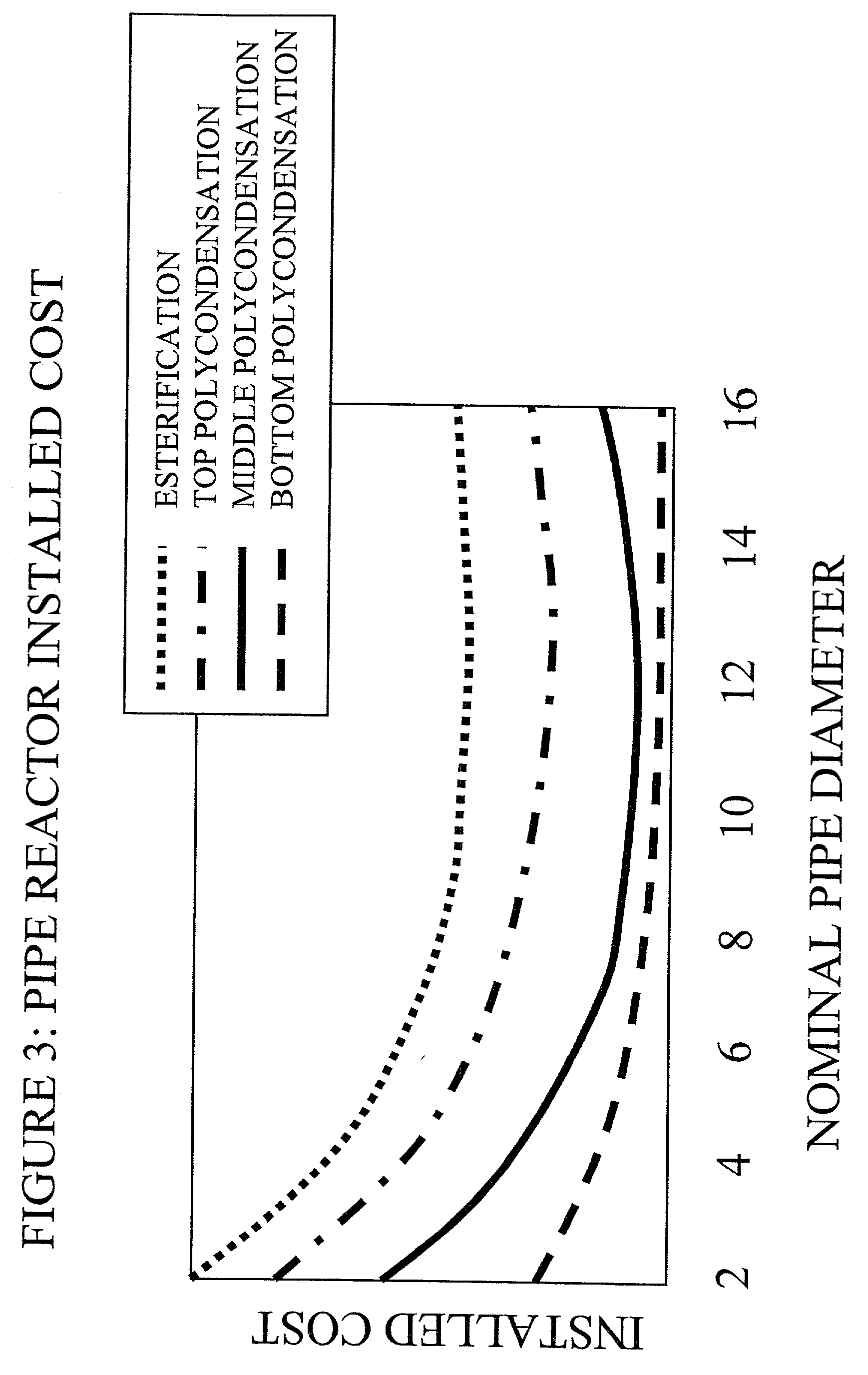
These higher surface area zones will affect the cost of the pipe reactor.
Slug and plug flow risk possible equipment damage, annular and disbursed provide too low a
residence time, and wavy flow entrains process liquid into the gas
stream, which causes
fouling in the gas handling equipment.
Countercurrent can provide for more efficient disengagement but presents equipment
layout disadvantages.
These pockets reduce the reaction area, thereby
reducing capacity, and in cannot be readily drained during the process.
The vapor will condense on the solids and the mixture will be very sticky and plug the
system.
Prior to the instant invention, vapors would condense on the solids and the mixture would become very tacky, thus resulting in the clogging of the entire
system.
In fact, pipe reactors that process only fluid reactants may not benefit from the added complexity of including the recirculation loop.
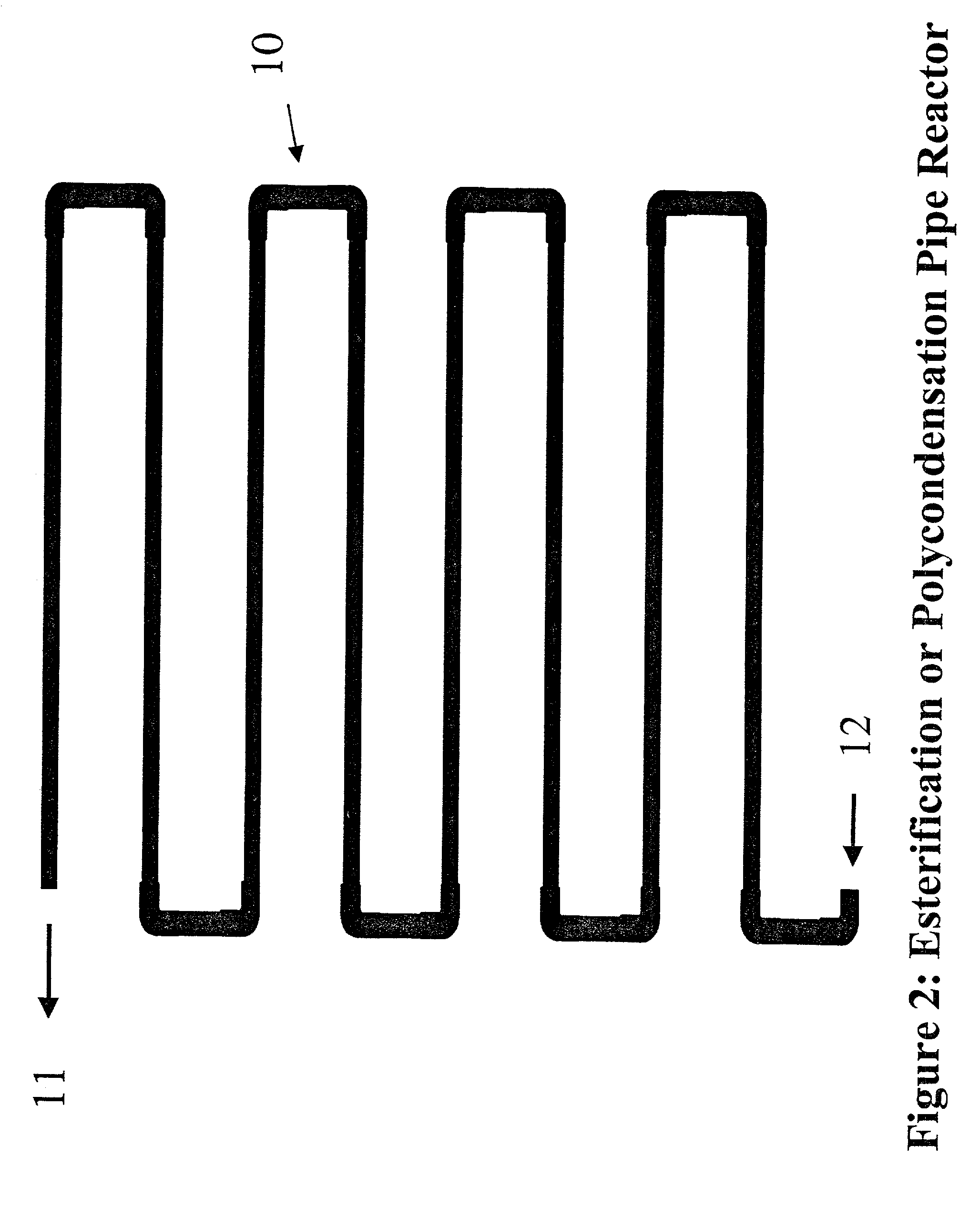
The upper length limit is only limited by the practical amount of horizontal space available at the production facility.
However, with only one vacuum
system, the vapor velocities can be extremely high and will detrimentally put liquid with the vapor into the vacuum system.
The polycondensation pipe reactor actually dampens inlet perturbations despite eliminating the use of pumps.
Once the fluid in the reactor is so thick that a weir is not required to maintain level, then maintaining the pipe half full does not maximize surface area or
mass transfer rates.
This system does not normally have a purge, and the impurities generally leave on the
pellets, although this can cause problems.
The standard
cooling tower header does not supply enough pressure to go through the high-pressure drop coolers on the HTM pumps.
1.) use supply water as once through cooling
2.) increase the pressure of the
cooling tower water header paying the increased capital and pumping costs
4.)
purchasing low pressure drop coolers for the pumps incurring the added
capital cost and voiding the warrantee.
However, after passing through the HTM pumps the water should not come back to the cutter system since an HTM leak would contaminate the product.
The third vacuum stage cannot be integrated because the pressure in this stage is too high and would not otherwise allow the EG vapor jet to have the proper
differential pressure for operation.
Putting a valve in the vapor line has led to plugging problems and is not a reliable solution.
Alternately, steam or other hot condensable vapor may be used, but this detracts from the purity of the exiting
stream and also requires additional separation equipment for the
stream.
The pump overcomes the pressure drop between the two reactors since the
pressure difference is not great enough to provide the required flow.
In addition, the pipe reactor has no level or
pressure control systems to provide upsets to the system that would be dampened by the
gear pump.
For large plants, it may not be possible to acquire large enough pipe
diameter to construct the reactor and meet the parameters.
Thus, the only additional equipment, and cost incurred, is the additional
piping required.

