
Diamond-coated member

Inactive Publication Date: 2003-04-03
NGK INSULATORS LTD
View PDF11 Cites 54 Cited by
  • Summary
  • Abstract
  • Description
  • Claims
  • Application Information

AI Technical Summary

Problems solved by technology

In other words, the preparation of a highly pure material with no impurities would become meaningless if a substrate or a chip is contaminated in the course of its processes with impurities derived from phenomenon other than the intended reactions, such as, corrosion of members or increased elution from the members in a supply channel to a production apparatus or in the production apparatus.
This is a problem to be solved for members of a semiconductor producing apparatus.
These gases are corrosive.
However, as gases for use in CVD become more corrosive, more undesirable impurities such as oxides, chlorides and fluorides generated by reactions with metal increase, and heaters lose their durability.
However, since this heater uses indirect heating, it has problems such as large heat loss, increase in operation costs, a time-consuming period for raising temperature, and reduction in throughput.
Moreover, a thin film by CVD adheres to an infrared ray transmitting window, causing such problems as increasing hindrance to infrared ray transmission, resultantly heating of infrared ray transmitting window, and so forth.
The time spent on maintenance was also rather long.
Moreover, since a susceptor to be heated is made of graphite or the like, corrosion is inevitable even in this type.
When the erosion of members is accelerated by ion bombardment of plasma; or member components are sputtered by ion bombardment of plasma, a substrate will be contaminated.
As the design rule is further miniaturized to nearly 0.1 .mu.m, such a problem becomes more apparent than before.
Additionally, since high frequency power to generate plasma is rising, even erosion resistant members are bombarded with ions and thus exposed to a harsher environment while being heated at high temperature.
However, as the heater and the supporting member are made of dense and gas tight ceramics such as aluminum nitride and sialon as a material, they do not generate impurities.
Furthermore, although diamond is expensive, it can be used practically by using it in a form of thin coat like this, with overcoming economic difficulties.
However, the object members of diamond or diamond-like carbon coating are limited to an electrostatic chuck and a chamber in those proposals.
Diamond is composed of carbon atoms, so that it has chemical weaknesses assumed from the fact, for instance, that it is easily oxidized under a high-temperature air to form carbon dioxide and thus, dissipating.
Therefore, one may not judge clearly that diamond can show sufficient corrosion resistance over a long period under high temperature according to JP-A-10-70181 and JP-A-10-96082.
Diamond has excellent corrosion resistance, but is costly.
Also, with a multilayer structure, electromagnetic characteristics vary when thinning occurs due to corrosion or the like, so that deterioration may be detected.
However, it is such a thin film that thermal conductivity little improves as a thin film on a member.
When a surface layer does not permit light permeation, in other words, when a surface layer itself controls emissivity, it will be difficult to uniformly control film properties.
Additionally, since emissivity also normally relies on a film thickness or wavelength, thermal uniformity will be uneven.
Also, with a multilayer structure, deterioration may be detected.
However, it is such a thin film that thermal conductivity does not improve much as a thin film formed on a heater.
On the contrary, when the surface is too smooth, heat transmission efficiencies become too different between parts where the diamond thin film is contacting and is not contacting.
The arc jet method is also unlikely to provide adhesion, and the corrosion-erosion resistance of a diamond thin film seems inferior.
Also, with a multilayer structure, deterioration may be detected.
However, it is such a thin film that thermal conductivity does not improve much as a diamond film formed on a ring.
On the contrary, when the surface is too smooth, heat transmission efficiencies become too different between parts with and without the diamond thin film.
In the arc-jet method, adhesion is week, and corrosion-erosion resistance of the diamond thin film shows up badly in comparison.

Method used


Image

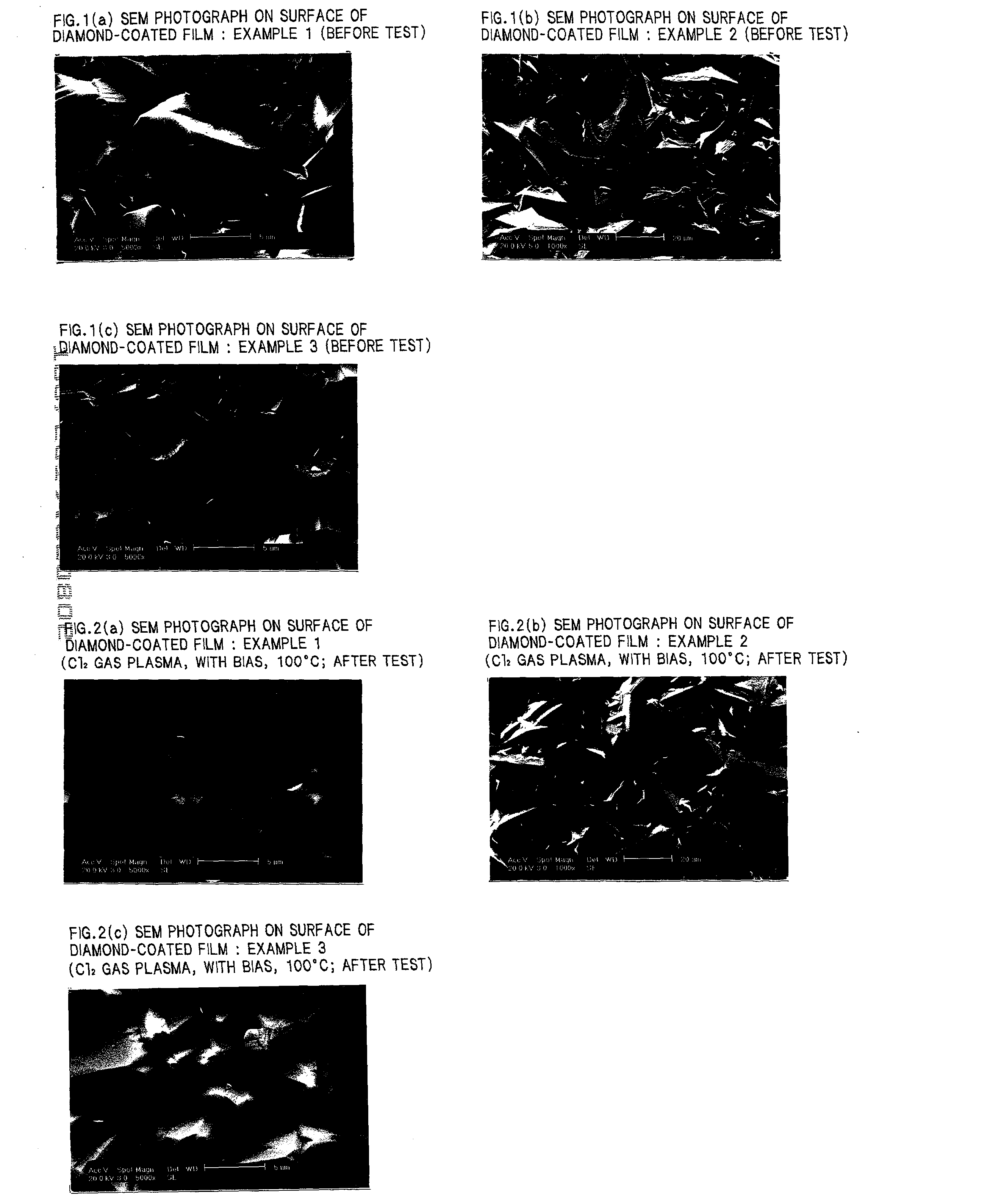
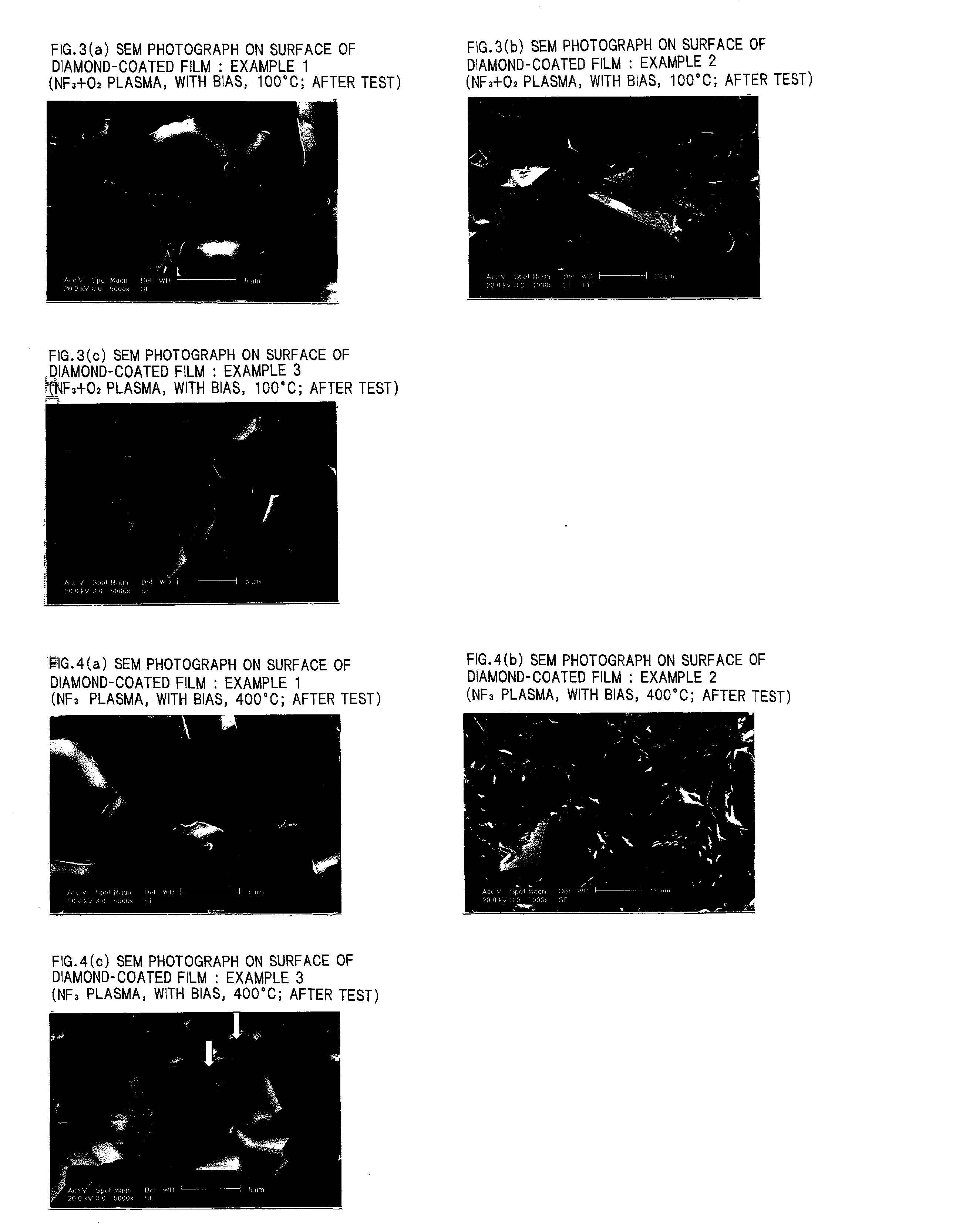
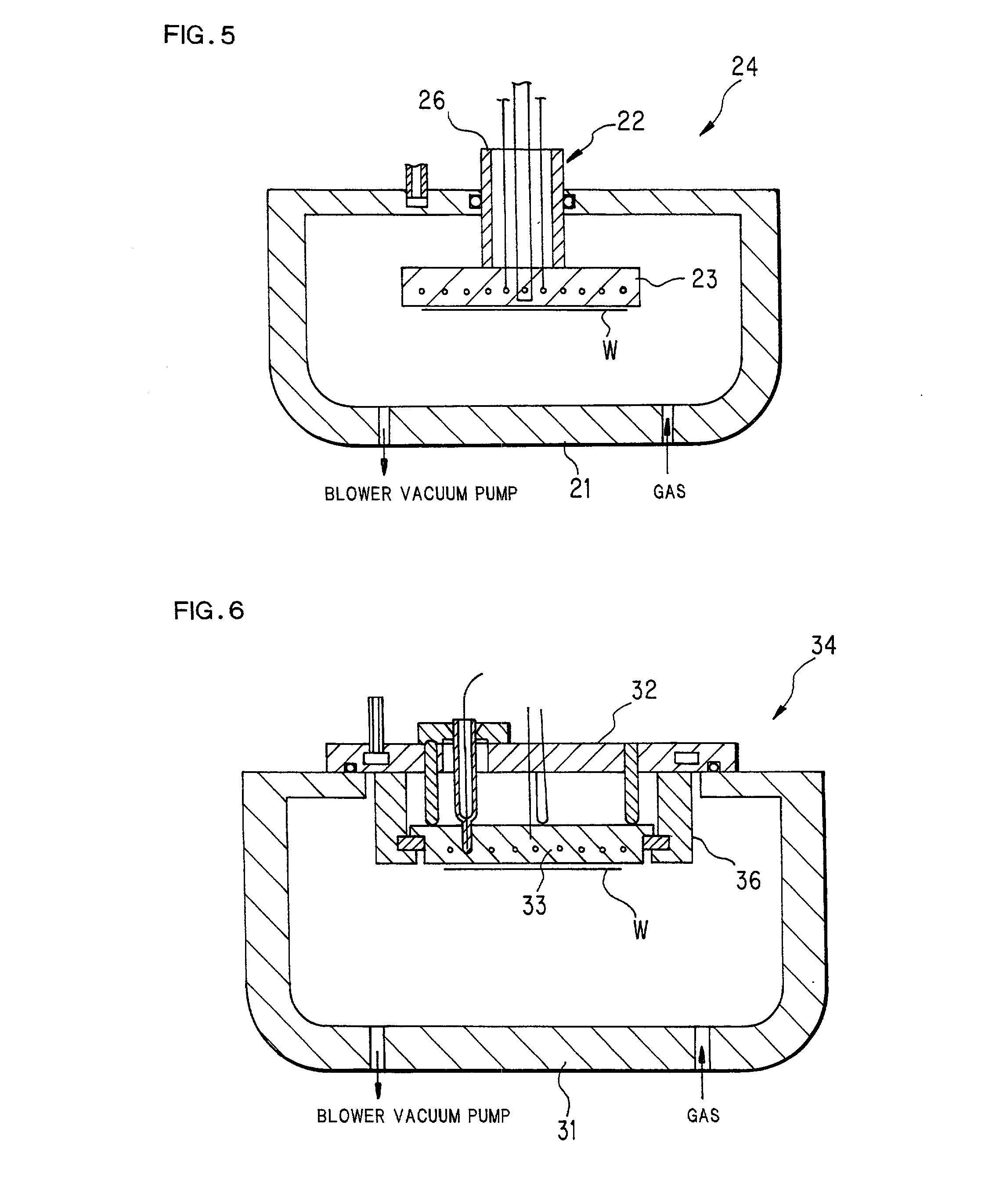
  • Diamond-coated member
  • Diamond-coated member
  • Diamond-coated member

Examples


examples 4-7

[0118] Subsequently, 5 wt. % of yttrium oxide was added as a sintering aid. An aluminum nitride sintered body compacted by hot pressing in nitrogen was prepared, and was cut into small pieces of 20 mm W (width).times.20 mm L (length).times.2 mm t (thickness) shape by using a diamond grinding stone. To the small pieces, silicon carbide was coated as an intermediate layer at 100 .mu.m thickness by CVD (Example 4). Also, as an intermediate layer, a 1 .mu.m-thick silicon nitride was coated by sputtering method (Example 5). Furthermore, metal silicon was coated at about 100 .mu.m-thickness by a plasma-spraying method (Example 6). In Examples 4 to 6, 15 .mu.m-thick diamond films were deposited by microwave CVD using hydrogen, oxygen as a starting gas. Basal material temperature in a film forming process was 740.degree. C.

[0119] All crystal phases in Examples 4 to 6 were diamond phase with a minor non-diamond phase. Also, the degrees of orientation were 0.70 in Example 4, 0.63 in Example 5...

examples 14 , 15

Examples 14, 15, Comparative Example 5

[0140] Then, three each of the ring made of silicon nitride (Example 14) and ring made of silicon carbide (Example 15) in the same shape as the rings in Examples 11 to 13 were prepared. For a final finish, a diamond grinding stone was used. In Example 14, ceria (CeO.sub.2: cerium oxide) was added at 5 wt. %, and was sintered by hot pressing in nitrogen atmosphere, and was compacted up to the theoretical density ratio of 99% or more. The content of the elements of the group 1a and the groups 4a to 3b in a sintered body is less than 50 ppm. In Example 15, 1 wt. % of boron and 0.5 wt. % of carbon were added, and were similarly compacted to 95% or more in argon atmosphere by hot pressing. The content of the elements of the group 1a and the groups 4a to 3b, except for boron, is less than 50 ppm.

[0141] Three each of ring of Example 14 and Example 15 were prepared, and a diamond film was deposited by the same method as in Example 1 until the thickness ...

example 16

[0148] There is provided a heater shown in FIG. 10 (Example 16) which is the same heater as in Example 8, but has no basal material between a high frequency electrode and a diamond film, and directly coated with diamond on the electrode. Exemplarily, the same heater as in Example 8 was prepared, and the film on a heating face was removed with a diamond grinding stone, thereby a molybdenum mesh high frequency electrode was exposed. Aluminum nitride as a basal material was in the openings of the mesh. Subsequently, a diamond film was formed at about 15 .mu.m thickness by the same method as in Example 1.

[0149] As in Example 8, preferable results were obtained. This method is preferable in that the diamond film itself operates as a high frequency electrode. That is, in ordinary ceramic heaters, a high frequency electrode has to be embedded in a ceramic basal material to protect the electrode from corrosive gas. However, diamond has some conductivity, so that it also operates as a corros...


PUM

PropertyMeasurementUnit
Fractionaaaaaaaaaa
Fractionaaaaaaaaaa
Fractionaaaaaaaaaa

Abstract

A diamond-coated member includes a basal material such as aluminum nitride, and a diamond thin film coating at least one part of a surface of the basal material, being adhered thereto, and has corrosion-erosion resistance. Adhesion strength between the thin film and the basal material is 15 MPa or more. Or, in diamond thin film, degree of orientation of diamond {220} plane present in faces parallel to the basal material is expressed by following formula: [Im220 / (Im220+Im111)] / [Ip220 / (Ip220+Ip111)]<1. The diamond-coated corrosion-erosion resistant member has excellent corrosion-erosion resistance, and is used mainly for a semiconductor producing apparatus; being preferably applied as a member inside a reaction chamber where a substrate, represented by silicon wafer, is exposed to plasma, corrosion gas or the like, inclusive of rings, a chamber inner lining, a gas shower plate, nozzles, a susceptor, an electrostatic chuck, a heater, or the like.

Description

BACKGROUND OF THE INVENTION AND THE RELATED ART[0001] The present invention relates to a diamond-coated member mainly used for a substrate treating device, the member having excellent corrosion-erosion resistance. More specifically, the present invention relates to a diamond-coated member which is preferably used particularly as a member in a reaction chamber where a substrate, represented by a silicon wafer, is exposed to plasma, corrosive gas or the like--involving, for instance, rings, a chamber inner lining, a gas shower plate, nozzles, a susceptor, a dome, a bell-jar, an electrode, a heater, and so forth--and which is made more useful as a member exposed to plasma at high temperature by providing orientation thereto.[0002] The current of the IT Revolution, following the agrarian revolution and the industrial revolution, is surging. To further develop the economy and promote an affluent and vibrant society in 21.sup.st century, one theme is to reform the socioeconomic structure ...

Claims


Application Information

Patent Timeline
IPC IPC(8): C23C16/27C30B29/04C23C16/458C23C16/46C30B25/10H01L21/205H01L21/68H01L21/683
CPCC23C16/27C23C16/4581C23C16/46C30B25/105H01J37/32504Y10T428/30H01J37/32642H01L21/6833H01J37/32559C30B29/04
Inventor OHASHI, TSUNEAKIMURAI, MAKOTOKOBAYASHI, HIROMICHI
Owner NGK INSULATORS LTD
Learn More