Composite refractory metal carbide coating on a substrate and method for making thereof

Inactive Publication Date: 2005-03-24
GENERAL ELECTRIC CO
View PDF9 Cites 118 Cited by
  • Summary
  • Abstract
  • Description
  • Claims
  • Application Information

AI Technical Summary

Benefits of technology

[0010] The invention relates to a composite coating for use on articles or components subject to high-temperature and corrosive (harsh) processing environments, the composite coating comprising a refractory metal carbide coating having its surface modified by at least one of: a) carburizing by a carbon donor source for a stabilized stoichiometry, with the metal carbide being selected from the group consisting of silicon carbide, tantalum carbide, titanium carbide, tungsten carbide, silicon oxycarbide, zirconium carbide, hafnium carbide, lanthanum carbide, va

Problems solved by technology

Graphite however has certain disadvantages including impurities, poor durability in corrosive environment, and the tendency to degrade and microcrack in environments requiring exposure to repeated temperature cycles.
Such microcracking and degradation adversely affect dimensional stability and product quality.
In addition, contamination of the product may occur by the leaching of

Method used


Image

  • Composite refractory metal carbide coating on a substrate and method for making thereof
  • Composite refractory metal carbide coating on a substrate and method for making thereof
  • Composite refractory metal carbide coating on a substrate and method for making thereof

Examples


example 1

[0059] This example encompasses a 3-step process and illustrates the coating characteristics as a result of each step.

Process Conditions: Temperature, time,gas & flow rates, pressure (Gas Flows inProcess Stepslpm; P = pressure)SubstrateNotes1. TaC CoatingHeat up 25-2300° C. in 2-4 hours atGraphiteTaC (15-20 μm thick)on Graphitelow pressures (4-8 mm) under nitrogencoating on surface that isflow (˜2-4 liter per minute)Ta rich at the surface withInject TaC15 vapors and chlorineTa / C atomic ratio of ˜1.5-2300C 100 mm 6 hours1.7 in a 1000 AngstromPurge with N2 and coolthick surfacelayer2. CarburizationHeat Up 25-1600° C. in 60-90 min;TaC coatedDark grey colorof TaC / GraphiteAr = 0.5 lpm; P = 0.5 Torrgraphitegraphite nodules at grain1600C 20 min; CH4 = 0.5 slpm, Ar = 0;boundary. Typical weightP = 0.5 Torrgain = ˜40 mg / 100 cm2.1600C 2 hrs; Ar = 0.5; P = 0.5 Torr(1-2 μm thick)3. NH3Heat Up 25-1400° C.; 20 min; N2 = 0.5,CarburizedWeight Loss ˜0.75ExposureP-250 μ.mTaC coatedmg / 100 cm2.or remo...

example 2

[0061] A graphite substrate is coated with tantalum carbide coating by following process step #1 in Example 1. After checking for coating quality, the coated substrate is heated in a graphite vacuum furnace to 1600° C. in nitrogen. After the temperature is stabilized, methane is introduced for 20 minutes.. This step is followed by diffusion annealing in nitrogen for one hour. In the final step, the coated substrate is exposed to ammonia for a period of 10 minutes as described in Step 3 of Example 1 to remove excess carbon. These steps are repeated five times to build up a strong, coherent, corrosion resistant carbon rich layer of high emissivity. The process temperature may be selected in a range of 1400 to 1800° C. depending on the process time, as lower temperature requires longer annealing time than at a higher temperature. The steps in Example 2 are summarized below.

ProcessStepProcess ConditionsSubstrateNotesCoatingA: Heat up to 1600° C. inTantalum carbidewith TaC2.5 hours, pr...

example 3

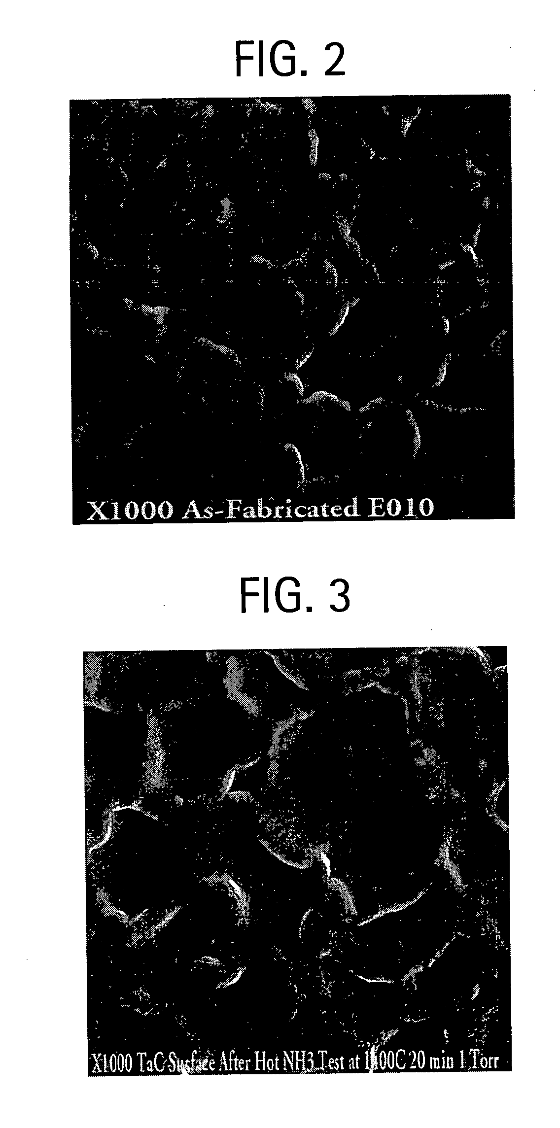
[0065] In this example, the coating of Example 2 is exposed to ammonia at 1400° C. for 20 min under 1 torr pressure. FIG. 3 is a micrograph of the TaC coating after hot NH3 test at high temperatures. Similar to the TaC coating as shown in FIG. 2, the grains of TaC in Example 3 with raised thick grain boundaries are clearly observed in the micrographs, and there is no detectable change in the microstructure as a result of hot ammonia exposure.


PUM

PropertyMeasurementUnit
Fractionaaaaaaaaaa
Fractionaaaaaaaaaa
Percent by atomaaaaaaaaaa

Abstract

A composite coating for use on semi-conductor processing components, comprising a refractory metal carbide coating with its surface modified by at least one of: a) a carbon donor source for a stabilized stoichiometry, and b) a layer of nitride, carbonitride or oxynitride of elements selected from a group B, Al, Si, refractory metals, transition metals, rare earth metals which may or may not contain electrically conducting pattern, and wherein the metal carbide is selected from the group consisting of silicon carbide, tantalum carbide, titanium carbide, tungsten carbide, silicon oxycarbide, zirconium carbide, hafnium carbide, lanthanum carbide, vanadium carbide, niobium carbide, magnesium carbide, chromium carbide, molybdenum carbide, beryllium carbide and mixtures thereof. The composite coating is characterized as having an improved corrosion resistance property and little emissivity sensitivity to wavelengths used in optical pyrometry under the normal semi-conductor processing environments.

Description

[0001] This patent application claims priority on provisional application U.S. Ser. No. 60 / 482,532 with a filing date of Jun. 25, 2003.FIELD OF THE INVENTION [0002] This invention relates to a composite refractory metal carbide coating on a substrate for use as a component in semiconductor processes, and to a method of forming said coating. BACKGROUND OF THE INVENTION [0003] In a process to grow nitride crystals such as GaN, a gaseous hydride source, e.g., ammonia NH3, is used as a feed source for the growth of the nitride on a substrate such as sapphire. The substrate usually rests oil a block called a susceptor that can be heated by a radiation frequency (RF) coil, resistance heated, or radiantly by a strip heater. The function of the susceptor is to support a substrate, on which a thin film of a functional crystal is deposited or to hold a crucible (usually quartz in the silicon crystal growing process), which is in intimate contact with the crystal melt. The susceptor must also ...

Claims


Application Information

Patent Timeline
IPC IPC(8): B05D7/22B32B9/00C23C16/14C23C16/36C23C16/458C23C16/56H01L21/00
CPCC23C16/36Y10T428/24917Y10T428/30C23C16/4581C04B41/009C04B41/89C04B2111/00844C04B41/52C04B35/522C04B41/4531C04B41/5057C04B41/5001C04B41/5063C04B41/522C23C16/14H01L21/00C23C16/56
Inventor SANE, AJITLENNARTZ, JEFFREYLEIST, JONKOTABISH, DANIELMARINER, JOHNMACEY, ANDREWLONGWORTH, DOUGLASHEJL, TIMOTHYDEVAN, THOMAS
Owner GENERAL ELECTRIC CO
Why Eureka
Try Eureka