Further, to increase the rotation speed, there are difficult technical issues such as improvement of the bearing of the polygon mirror.
However, when images are formed using such a multi-beam
irradiation method, a drawback occurs such that the density, breadth and size of line images and dot images may vary depending on whether adjacent beams are emitted simultaneously or separately.
Image bearing members may show reciprocity failure depending on how the energy is provided thereto even when the same
irradiation energy is provided.
Therefore, the amount of the charges movable becomes relatively small, resulting in reduction of the sensitivity; and (4) Also, when the intensity of the
electric field applied to a photosensitive layer is low, the amount of the charges accumulated per unit space increases, which leads to rise in the probability of reunion of charges.
Therefore, the amount of the charges movable becomes relatively small, resulting in reduction of the sensitivity.
As a result, decrease in the sensitivity of the photosensitive layer due to the reciprocity failure is small.
However, these technologies accompany device improvement, which leads to cost increase.
However, when the electroconductive layer is in a direct contact with the photosensitive layer, the charge potential of an image bearing member tends to attenuate.
Especially, when an image is formed based on reversal development, a drawback arises such that background
fouling such as black spots is observed in the background portion in an image.
This drawback significantly emerges while
image formation is repetitively performed.
However, while
image formation is repetitively performed, the charges are accumulated in the intermediate layer, which leads to increase in the potential of the irradiated portion of the image bearing member.
This causes a drawback such that electrostatic contrast (the difference between the
voltage at the non-irradiated portion and the
voltage at the irradiated portion), which is necessary to form images, becomes small.
However, the plane emission
laser has relatively a small power in comparison with a typical end face emission
laser.
Therefore, when the sensitivity of an image bearing member lowers while
image formation is retentively performed, abnormal images and non-uniform images as mentioned above significantly occur.
However, it is found to be difficult to sufficiently deal with the drawback as mentioned above just simply by regulating the
specific resistance of the intermediate layer when image formation is performed in a large amount with a linear velocity of at least 300 m / s of the image bearing member.
However, in both cases, it is found to be difficult to sufficiently deal with the drawback as mentioned above when image formation is performed in a large amount with a high linear velocity of, for example, at least 300 m / s, of the image bearing member.
However, a typical image bearing member containing a known titanyl
phthalocyanine has a difficulty in that such an image bearing member has a
short life because residual charges easily remain in the image bearing member while the image formation process, especially the charging process and the
irradiation process, is repeated.
In addition, the accumulated remaining charges substantially weaken the intensity of the
electric field applied to the photosensitive layer contributing to the sensitivity of the image bearing member, which promotes reciprocity failure.
This causes non-uniformity between the simultaneously irradiated portion and sequentially irradiated portion mentioned above when an image is formed by a multi-beam recording in which multiple
laser beams are emitted.
Especially, when a plane
light emission laser, which has a relatively small light power, is used as a multi-beam irradiation
light source, non-uniformity in an image becomes significant due to deterioration of the sensitivity and reciprocity failure ascribable to the increase of residual charges in an image bearing member.
Therefore, when the durability of an image bearing member, which is a main device in the image formation process, is low, it is inevitable that such an image bearing member is frequently replaced.
This causes problems such that the substantial time to be taken to print images is long and image formation cost increases.
This is considered to be because, as the
irradiation time to be taken per dot decreases, the light power of a laser is strengthened, resulting in significant reciprocity failure phenomenon of the image bearing member.
However, as described later, known titanyl
phthalocyanine has various kinds of deficiencies for use under an
electric field having a strong intensity.
Especially, such titanyl phthalocyanine is not suitable for multi-beam irradiation under an electric field of 30 V / μm or higher.
Therefore, such an image forming apparatus is extremely large unless the image bearing member and each device therearound are compact in size.
When an image bearing member having a small
diameter has an extremely
short life in comparison with an image bearing member having a large
diameter, the merit in
size reduction of an image forming apparatus having such an image bearing member is lost.
Therefore, elongating the life of such an image bearing member in comparison with that of a typical image bearing member is recognized as a technical issue.
One is electrostatic fatigue and the other is the wear of the
surface layer thereof.
Either of these two limiting factors is a significant issue for a currently popular organic image bearing member.
When an image bearing member formed of an organic material is used, it is typical that the decrease in the charging
voltage or the rise in the voltage at irradiated portions is a problem.
Therefore, the thickness of this
surface layer decreases, which leads to
vulnerability to damage to the image bearing member, rise in the intensity of the electric field and acceleration of electrostatic fatigue.
This makes the life of an image bearing member extremely short.
The problem of abnormal images
stemming from electrostatic fatigue is caused by deterioration of an image bearing member.
However, some image bearing members locally have a portion easily leaking its
surface charges.
The toner is thus attached to the local portion having a
low voltage, resulting in the background
fouling.
There are causes to this background
fouling.
However, such a single intermediate layer formed of a simple resin has a high electric resistance, which causes the residual potential to rise.
As a result, the
image density deteriorates in a negative positive development.
Therefore, the background fouling tends to occur.
Actually, the background fouling is not sufficiently restrained.
In addition, there is a problem that, when these resin
layers are used in an image forming apparatus of late years using coherent light such as a laser beam, moiré is observed in images obtained.
Consequently, it is difficult to have a good combination of reducing
residual voltage and decreasing background fouling.
In addition, when the content of a resin is small, the
adhesive property between the intermediate layer and an electroconductive substrate deteriorates, which easily causes detachment thereof.
Especially, this has a fatal effect on an image bearing member formed of an electroconductive substrate having a flexible belt form.
However, only the resin layer restrains the carrier infusion from the electroconductive substrate.
When the resin layer is thinned, the background fouling increases.
Therefore, it is not satisfying in terms of achieving a good combination thereof.
Therefore, it is difficult to restrain the occurrence of background fouling by raising the resistance of a filler contained in the filler dispersed layer because the influence of the residual potential extremely increases.
However, it is difficult to sufficiently restrain the occurrence of background fouling simply by accumulating an electroconductive layer and an intermediate layer.
However, since the resin layer is desired to be thickened, background fouling and residual potential tend to be greatly dependent on a combination of
humidity and / or the
layer thickness and a resin used in the resin layer.
As a result, the structure is devoid of high stability.
Further, in addition to charge (positive hole) infusion from an electroconductive substrate to a photosensitive layer, the influence of the generation of heated carrier in the photosensitive layer is not ignorable as the cause of the occurrence of background fouling.
Therefore, background fouling caused during repetitive use cannot be fully controlled without suitably selecting a charge generating material used in a charge generating layer and controlling the state of the particles thereof.
However, this
crystal type is unstable as a
crystal and has a drawback in that the crystal form has a low stability and is vulnerable to mechanical stress and thermal stress during dispersion, etc., and easily transferred to another crystal form.
In addition, especially abnormal images having background fouling
stemming from the negative positive development easily occur while an image bearing member is repeatedly used.
That is, background fouling becomes obvious.
Contaminants contained in titanly phthalocyanine cause extreme reduction in the amount of charges and increase of dark decay due to fatigue, resulting in deterioration of anti-background fouling property.
However, when the intensity of an electric filed applied on an image bearing member is small, the optical carrier generated in a photosensitive layer spreads due to
Coulomb repulsion.
When the surface potential of an image bearing member is low, the efficiency of development deteriorates.
However, an increased intensity of the transfer electric field causes discharging to the contrary, which may cause transfer toner scattering and accelerate the fatigue of electrostatic characteristics of an image bearing member.
However, when the definition of a writing laser beam increases, it is not possible to develop written dots with good reproducibility without setting the
lower limit thereof to be relatively high.
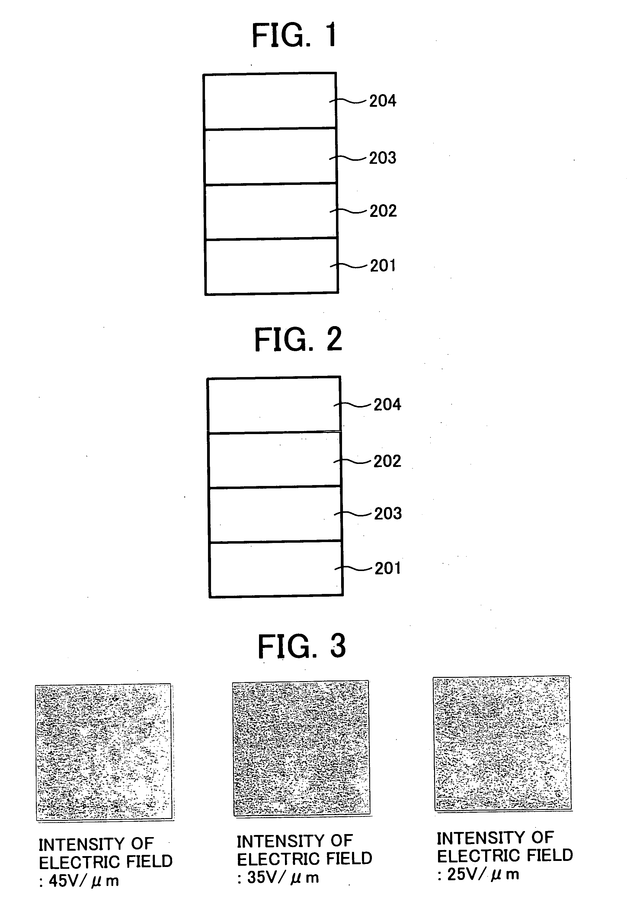
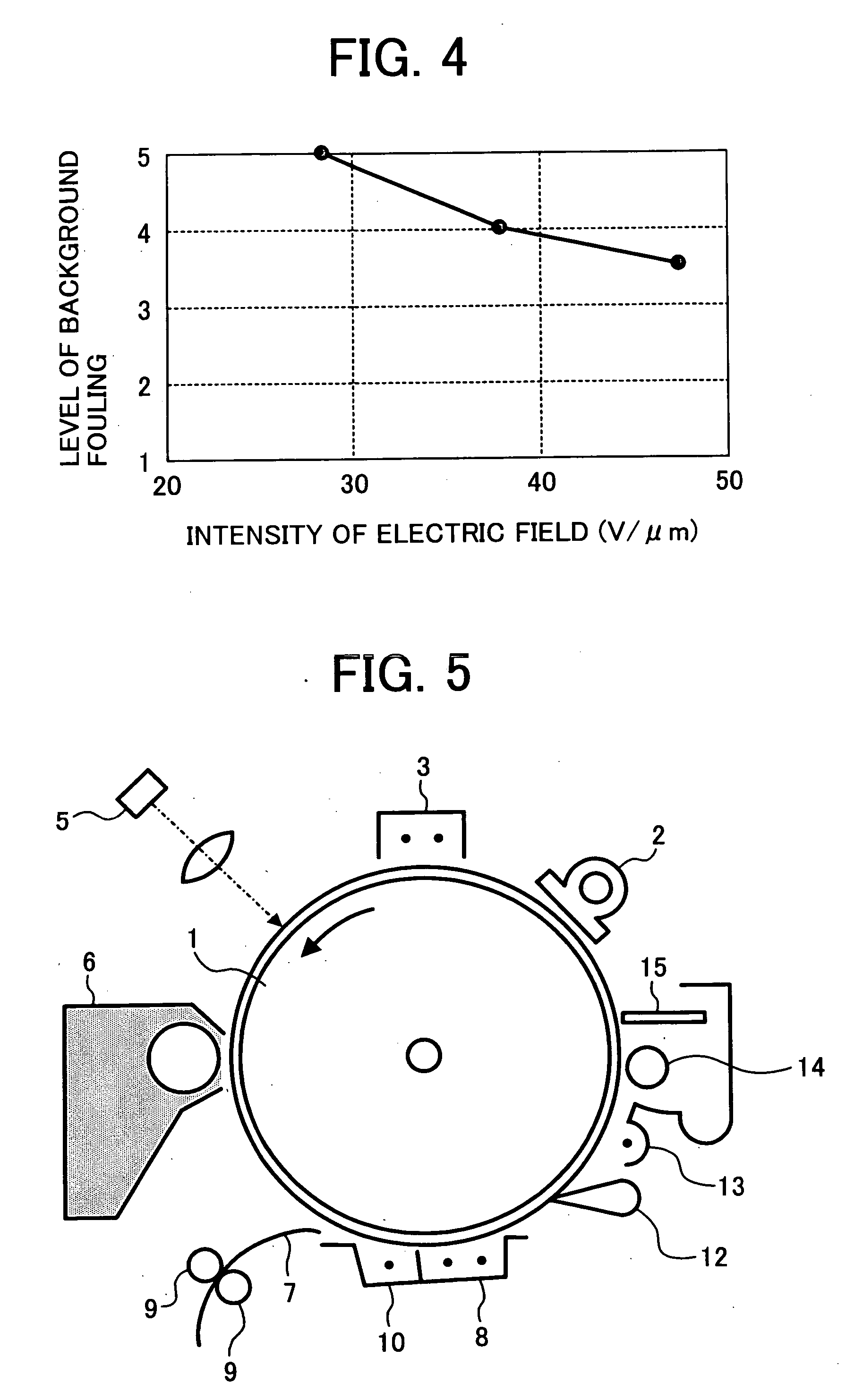
In addition, with regard to background fouling, the upper limit of the intensity of an electric field varies depending on the materials (mainly
charge generation material) forming an image bearing member.
The titanyl phthalocyanine having a CuKα
X ray (having a
wavelength of 1.542 Å)
diffraction spectrum such that at least the maximum diffraction peak is observed at a Bragg (2θ) angle of 27.3±0.2° has an extremely high sensitivity but has a drawback in that the titanyl phthalocyanine is not suitable on background fouling.
As the intensity of an electric field decreases, the optical carrier generating efficiency extremely worsens.
In the typical technologies, it is difficult to have a good combination of restraining background fouling and the rise in the residual voltage.
When the rise in the residual voltage is restrained, the effect on restraint of the background fouling is insufficient.
Furthermore, there is another factor having a great effect on the background fouling, which is the increase in the intensity of an electric field induced by the decrease in the
layer thickness of an image bearing member.
However, among these, the technology mentioned in (i): the curing binder resin, is not sufficiently compatible with a charge transport material.
In addition, the residual also tends to rise due to the existence of contaminants such as non-reacted remaining group and a
polymerization initiator.
Further, when the polymeric charge transport material mentioned in (ii) is used, the anti-abrasion property of an image bearing member can be improved in some degree but does not reach a desired level.
Further, polymerizing and refining a polymeric charge transport material is so difficult that the purity is not sufficient.
Therefore, the electric characteristics between materials are not easily stable.
Furthermore, there are problems relating to manufacturing such that the liquid for application has a high
viscosity.
However, the residual voltage rises due to charge trap, which is caused by the charge existing on the surface of the
inorganic filler.
Further, when the concavity and convexity of the
inorganic filler and the binder resin on the surface of an image bearing member is large, the cleaning performance deteriorates, which may lead to toner filming and image flowing.
These technologies (i) to (iii) have an effect on restraining background fouling but have a problem about the residual potential and cleaning performance, resulting in image deficiency.
Therefore, these technologies are not fully sufficient to improve the durability of an image bearing member.
In addition, when a charge transport material having a low molecular weight is simply contained in a
cross linkage type charge
transport layer, there arises a compatibility problem between the charge transport material and the curing material mentioned above.
Thereby, the charge transport material having a low molecular weight precipitates and causes clouding phenomenon.
Therefore, the rise in the irradiated portion voltage causes decrease in the image density and the
mechanical strength weakens.
Therefore, since a three-dimensional mesh structure is not
fully developed and naturally the cross-linkage density is thin, this type of an image bearing member does not have a drastically improved anti-abrasion property.
When a binder resin non-reactive to a charge transport material is used, the compatibility between the binder resin and a curing material formed in the reaction between the
monomer and the charge transport material is poor so that the layer detachment tends to occur in the cross-linkage type charge
transport layer, which may lead to damage or adhesion of external additives and
paper dust.
Further, as described above, since the three dimensional mesh structure is not
fully developed, and naturally the cross-linkage density is thin, this type of an image bearing member does not have a drastically improved anti-abrasion property.
Furthermore, a specific
monomer for this type of an image bearing member in the description has two functional groups so that the anti-abrasion property is not sufficiently improved.
Therefore, it is difficult to have a good combination of the amount and the density of the linkage of the charge transport material and the electric characteristics and anti-abrasion property are not sufficiently improved.
However, since the cumbersome positive hole transfer compound has at least two chain polymeric functional groups, the obtained cured compound tends to have
distortion therein and a high
internal stress.
Thereby, the cross-linkage
surface layer is vulnerable to
cracking and peeling for an extended period of use.
As described above, an image baring member having a cross-linkage photosensitive layer in which a charge transport structure is chemically bonded based on these typical technologies does not have sufficient comprehensive characteristics.
Since the background fouling is influenced not only by an undercoating layer but also by each layer such as a charge generating layer, a charge
transport layer and a protective layer, the background fouling is not sufficiently restrained and therefore the durability of an image bearing member is not achieved without improving each layer at the same time.
However, in the related typical art, there are few cases in which background fouling is restrained by each of the
layers forming an image bearing member.
In addition, in attempts to improve every layer at the same time, image deterioration drawbacks other than the background fouling frequently arise such that the residual potential rises, the dependency of chargeability and the residual potential on
humidity increases, and filming, image blur and image deficiency tend to occur.
That is, the durability of an image bearing member has not been highly improved.

