Coated implantable medical device

a medical device and coating technology, applied in the field of human and veterinary medical devices, can solve the problems of stenosis or occlusion of blood vessels, blood vessel walls can be disturbed or injured, stenosis or occlusion,

Inactive Publication Date: 2007-03-01
COOK MEDICAL TECH LLC
View PDF99 Cites 68 Cited by
  • Summary
  • Abstract
  • Description
  • Claims
  • Application Information

AI Technical Summary

Benefits of technology

[0012] The foregoing problems are solved and a technical advance is achieved in an illustrative vascular stent or other implantable medical device that provides a controlled release of an agent, drug or bioactive material into the vascular or other system, or other location in the body, in which a stent or other device is positioned. Applicants have discovered that the degradation of an agent, a drug or a bioactive material that is applied to such a device can be avoided by positing a coating layer on one surface of the device structure. The agent, drug or bioactive material is posited over at least a portion of the coating layer, wherein the coating layer provides for a controlled release of the bioactive material posited thereon. Furthermore, the medical device further includes a porous layer positioned over the bioactive material wherein the porous layer is composed of a polymer and the polymer provides for a controlled release of the bioactive material through the porous layer.

Problems solved by technology

However, when such a device is introduced into and manipulated through the vascular system, the blood vessel walls can be disturbed or injured.
Clot formation or thrombosis often results at the injured site, causing stenosis or occlusion of the blood vessel.
Moreover, if the medical device is left within the patient for an extended period of time, thrombus often forms on the device itself, again causing stenosis or occlusion.
As a result, the patient is placed at risk of a variety of complications, including heart attack, pulmonary embolism, and stroke.
Thus, the use of such a medical device can entail the risk of precisely the problems that its use was intended to ameliorate.
As the obstruction increases, a critical level of stenosis is reached, to the point where the flow of blood past the obstruction is insufficient to meet the metabolic needs of the tissue distal to (downstream of) the obstruction.
The result is ischemia.
While PTA presently enjoys wide use, it suffers from two major problems.
First, the blood vessel may suffer acute occlusion immediately after or within the initial hours after the dilation procedure.
Such occlusion is referred to as “abrupt closure.” Abrupt closure occurs in perhaps five percent or so of the cases in which PTA is employed, and can result in myocardial infarction and death if blood flow is not restored promptly.
A second major problem encountered in PTA is the re-narrowing of an artery after an initially successful angioplasty.
It has similarly been postulated that the delivery of appropriate agents directly into the arterial wall could interrupt the cellular and / or remodeling events leading to restenosis.
However, like the attempts to prevent thrombotic acute closure, the results of attempts to prevent restenosis in this manner have been mixed.
Restenosis of these lesions occurs at a high rate following angioplasty, however, due to the fibrotic nature of the diseases.
Medical therapies to treat or obviate them have been similarly disappointing.
Unfortunately, even when the implantation of the stent is accompanied by aggressive and precise antiplatelet and anticoagulation therapy (typically by systemic administration), the incidence of thrombotic vessel closure or other thrombotic complication remains significant, and the prevention of restenosis is not as successful as desired.
Furthermore, an undesirable side effect of the systemic antiplatelet and anticoagulation therapy is an increased incidence of bleeding complications, most often at the percutaneous entry site.

Method used


Image

  • Coated implantable medical device
  • Coated implantable medical device
  • Coated implantable medical device

Examples


Embodiment Construction

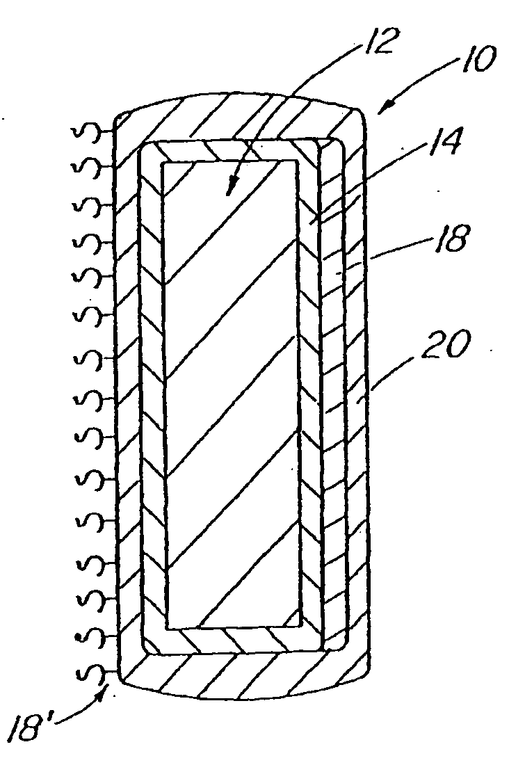
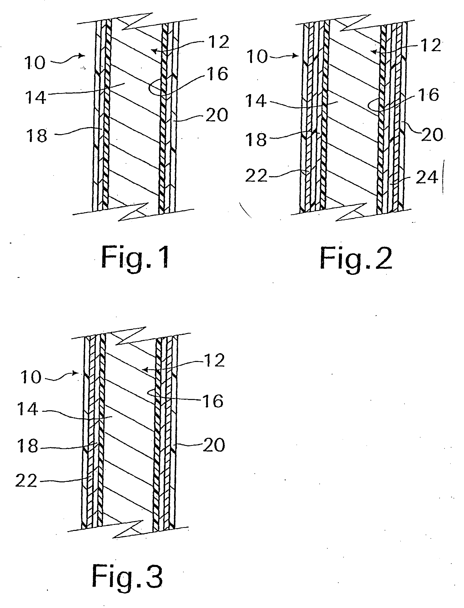
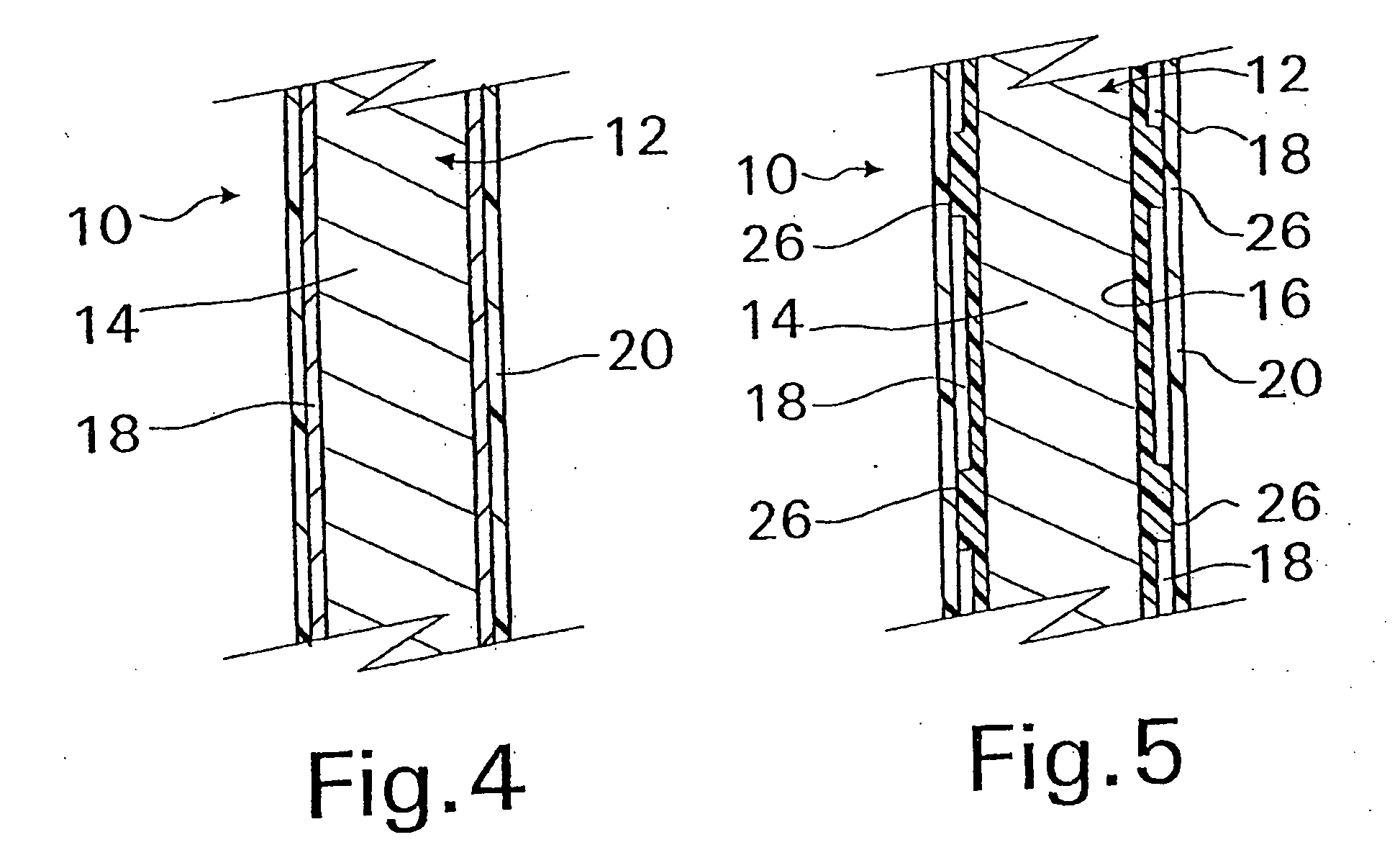
[0045] With reference now to FIG. 1, an implantable medical device 10 in accordance with the present invention is shown and first comprises a structure 12 adapted for introduction into a human or veterinary patient. “Adapted” means that the structure 12 is shaped and sized for such introduction. For clarity, only a portion of the structure 12 is shown in FIG. 1.

[0046] By way of example, the structure 12 is configured as a vascular stent particularly adapted for insertion into the vascular system of the patient. However, this stent structure can be used in other systems and sites such as the esophagus, trachea, colon, biliary ducts, urethra and ureters, subdural among others. Indeed, the structure 12 can alternatively be configured as any conventional vascular or other medical device, and can include any of a variety of conventional stents or other adjuncts, such as helical wound strands, perforated cylinders, or the like. Moreover, because the problems addressed by the present inve...


PUM

PropertyMeasurementUnit
thicknessaaaaaaaaaa
thicknessaaaaaaaaaa
thicknessaaaaaaaaaa

Abstract

A coated implantable medical device 10 includes a structure 12 adapted for introduction into the vascular system, esophagus, trachea, colon, biliary tract, or urinary tract; at least one coating layer 16 posited on one surface of the structure; and at least one layer 18 of a bioactive material posited on at least a portion of the coating layer 16, wherein the coating layer 16 provides for the controlled release of the bioactive material from the coating layer. In addition, at least one porous layer 20 can be posited over the bioactive material layer 18, wherein the porous layer includes a polymer and provides for the controlled release of the bioactive material therethrough. Preferably, the structure 12 is a coronary stent. The porous layer 20 includes a polymer applied preferably by vapor or plasma deposition and provides for a controlled release of the bioactive material. It is particularly preferred that the polymer is a polyamide, parylene or a parylene derivative, which is deposited without solvents, heat or catalysts, and merely by condensation of a monomer vapor.

Description

RELATED APPLICATIONS [0001] This application is a continuation-in-part of application Ser. No. 10 / 218,305, filed on Aug. 14, 2002, which is a continuation-in-part of application of application Ser. No. 09 / 027,054, filed Feb. 20, 1998, now U.S. Pat. No. 6,774,278, issued Aug. 10, 2004 which claimed priority to provisional application Ser. No. 60 / 038,459, filed Feb. 20, 1997, and which was also a continuation-in-part application of and claimed priority to application Ser. No. 08 / 645,646, filed May 16, 1996, now U.S. Pat. No. 6,096,070, issued Aug. 1, 2000, which was in turn a continuation-in-part application of and claimed priority to application Ser. No. 08 / 484,532, filed Jun. 7, 1995, now U.S. Pat. No. 5,609,629, issued Mar. 11, 1997.TECHNICAL FIELD [0002] This invention relates generally to human and veterinary medical devices, and more particularly to devices incorporating drugs or bioactive agents. BACKGROUND OF THE INVENTION [0003] It has become common to treat a variety of medi...

Claims


Application Information

Patent Timeline
Patent Type & Authority Applications(United States)
IPC IPC(8): A61F2/86A61F2/06A61F2/82
CPCA61F2/24A61F2/82A61N5/1002A61L2300/608A61L2300/606A61F2/885A61F2/91A61F2250/0068A61K51/1282A61L27/306A61L27/54A61L29/085A61L29/106A61L29/16A61L31/088A61L31/10A61L31/16A61L33/022A61L2300/256A61L2300/416A61L2300/602C08L65/04
Inventor BATES, BRIANRAGHEB, ANTHONYFEARNOT, NEALVOORHEES, WILLIAMKOZMA, THOMASGREWE, DAVIDSCHAEFFER, DARIN
Owner COOK MEDICAL TECH LLC
Why Eureka
Try Eureka