
Layered Core-Shell Cathode Active Materials For Lithium Secondary Batteries, Method For Preparing Thereof And Lithium Secondary Batteries Using The Same

a lithium secondary battery and active material technology, applied in the field of secondary lithium batteries, can solve the problems of high cost of cobalt components, inability to commercialize liniosub>2/sub>, and inability to meet the requirements of lithium secondary batteries, and achieve the effect of high capacity

Inactive Publication Date: 2008-08-14
SK ENERGY CO LTD (KR)
View PDF4 Cites 54 Cited by
  • Summary
  • Abstract
  • Description
  • Claims
  • Application Information

AI Technical Summary

Benefits of technology

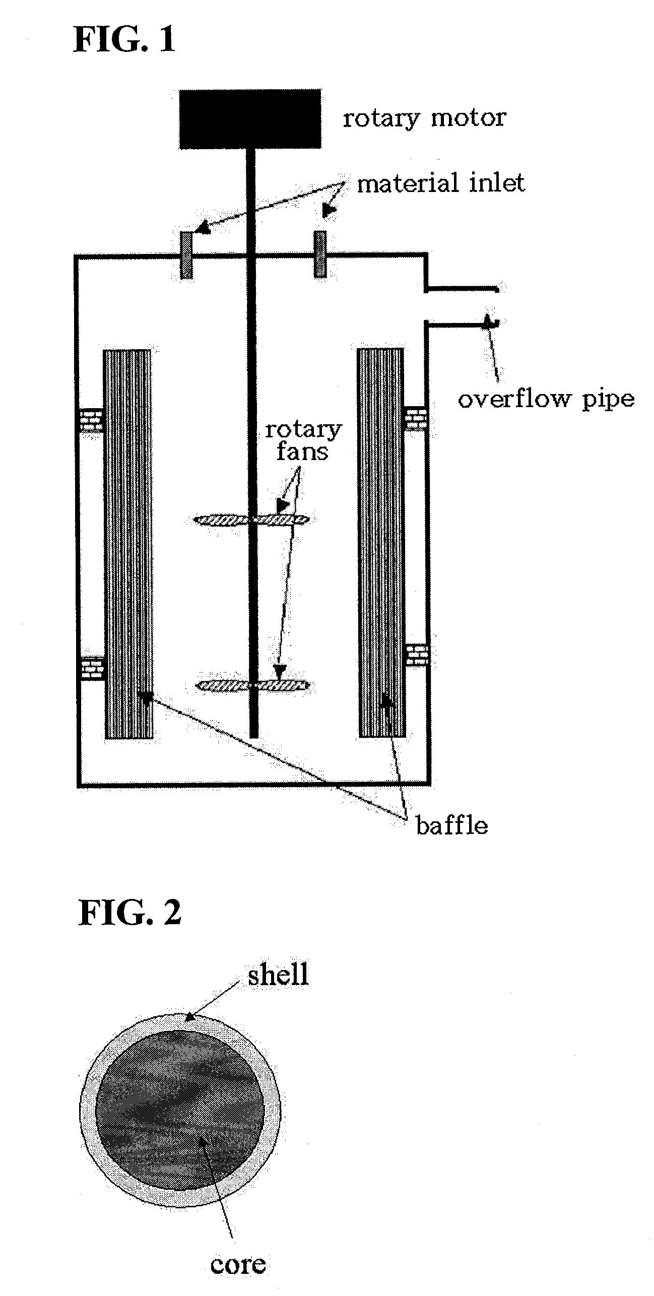
[0019]The bilayer core-shell cathode active material of the present invention is spherical and has a spinel structure. In the bilayer core-shell cathode active material, the inner part realizes the high capacity while the outer part is thermally stable, so that the electrode made from the active material is greatly improved with respect to capacity and lifetime.BEST MODE
[0020]In accordance with an aspect of the present invention, a spheric cathode active material for secondary lithium batteries, comprising a multilayer core-shell structure having a structural formula of: Li1+a[(MxMn1−x)1−z(M′yMn1−y)z]2O4 (M is selected from a group consisting of Ni, Co, Mg, Zn, Ca, Sr, Cu, Zr, P, Fe, Al, Ga, In, Cr, Ge, Sn and combinations thereof, M′ is selected from a group consisting of Ni, Mg, Cu, Zn and combinations thereof, M′ is different from M, 0.01≦x≦0.25, 0.01≦y≦0.5, 0.01≦z≦0.5, and 0≦a≦0.1) is provided.
[0021]In a modification of this aspect, the multilayer core-shell structure comprises a core having a structural formula of Li1+a[MxMn1−x]2O4 (M is selected from a group consisting of Ni, Co, Mg, Zn, Ca, Sr, Cu, Zr, P, Fe, Al, Ga, In, Cr, Ge, Sn and combinations thereof, 0.01≦x≦0.25, 0≦a≦0.1) and a shell having a structural formula of Li1+a[M′yMn1−y]2O4 (M′ is selected from a group consisting of Ni, Mg, Cu, Zn and combinations, 0.01≦y≦0.5, 0≦a≦0.1).
[0022]In another modification, the multilayer core-shell structure has a structural formula of Li1+a[MxMn1−x]1−z(MyMn1−y)z]2O4−bPb (P is F or S, 0.1≦b≦0.2).
[0023]In a preferred modification of the aspect, the shell is as thick as 3 to 50% of the total diameter of the cathode active material.
[0024]In another preferred modification of the aspect, the active material ranges in diameter from 1 to 50 μm.

Problems solved by technology

LiCoO2 shows stable charge and discharge characteristics, excellent electron conductivity, high stability, and flat discharge voltage characteristics, but the cobalt component is expensive because deposits thereof are few, and it is hazardous to the body.
LiNiO2 cannot be commercialized at present due to its difficulty in being stoichiometrically synthesized as well as its low thermal stability, although it has the same layered structure as LiCoO2.
LiMn2O4 incurs a low cost in the production thereof and is environmentally friendly, but shows poor lifetime characteristics due to the structural phase transition Jahn-Teller distortion, and Mn dissolution, both attributable to Mn3+.
Particularly, the Mn dissolution, resulting from the reaction of Mn with electrolytes, causes a great decrease in lifetime at high temperatures, acting as a hindrance to the commercialization of the rechargeable lithium ion battery.
However, crystals of the manganese carbonates thus obtained are not spherical, but are irregular in shape, with a broad particle distribution.
Such irregularly shaped manganese carbonates with a broad particle distribution have poor packing density and have a large specific surface in contact with the electrolytes, so that they dissolve in the electrolytes.

Method used


Image

  • Layered Core-Shell Cathode Active Materials For Lithium Secondary Batteries, Method For Preparing Thereof And Lithium Secondary Batteries Using The Same
  • Layered Core-Shell Cathode Active Materials For Lithium Secondary Batteries, Method For Preparing Thereof And Lithium Secondary Batteries Using The Same
  • Layered Core-Shell Cathode Active Materials For Lithium Secondary Batteries, Method For Preparing Thereof And Lithium Secondary Batteries Using The Same

Examples


example 1

[0064]1) Preparation of Spheric Manganese Carbonate

[0065]Into a coprecipitation reactor (capacity 4L, equipped with an 80 W rotary motor) was poured 4 liters of distilled water, followed by the addition of 80 ml of a 0.32 M hydrazine (H2NNH2) solution to the distilled water. Nitrogen gas was supplied at a rate of 1 liter / min to generate bubbles within the reactor, so as to remove dissolved oxygen while the reaction was maintained at 50° C. and stirred at 1,000 rpm.

[0066]Both a 1 M metal salt solution, in which manganese sulfate was mixed with magnesium sulfate at a 0.95:0.05 molar ratio, and a 0.5M aqueous ammonia solution were fed at a rate of 0.3 L / hr into the reactor. 5 liters of a 2M ammonium hydrogen carbonate (NH4HCO3) and 100 ml of a 0.32M hydrazine solution were mixed so as to adjust the pH of the reaction to 7.

[0067]An impeller was set to have a speed of 1,000 rpm to allow the solution to stay in the reactor for 6 hours on average. After the reaction reached a steady state,...

experimental example 1

Assay for Cathode Active Material Characteristics

[0074]The cathode active materials obtained in Example 1 and Comparative Example 1 were photographed using SEM and XRD.

[0075](1) SEM

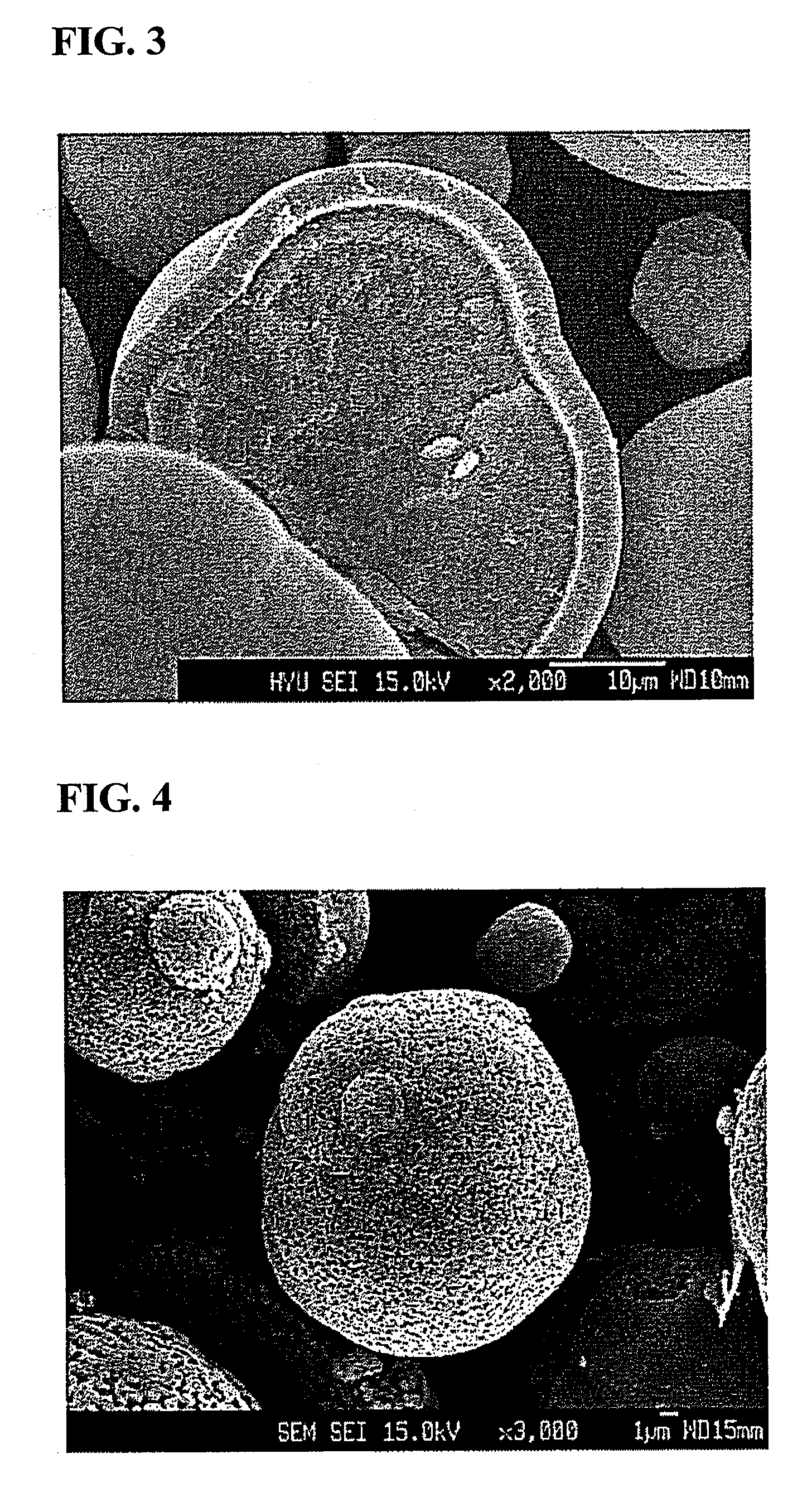
[0076]A SEM photograph of the bilayer spinel-type oxide particles obtained in Example 1 is shown in FIG. 4. As seen in this photograph, the particles were found to have a diameter of 30 μm or larger with a narrow particle size distribution, and to be spherical.

[0077]The bilayer core / shell structure of the particles is apparent from the cross section of the particle as shown in FIG. 3.

[0078](2) XRD

[0079]Using an X-ray diffractometer (Model Rint-2000, Rigaku, Japan), the particles were analyzed for X-ray diffraction patterns. XRD diffractograms of the precursor [(Ni0.5Mn1.5)x(Mn1.9Mg0.1)1−x]2O3 calcined at 500° C. and the cathode active material Li1+a[(Ni0.5Mn1.5)x(Mn1.9Mg0.1)1−x]2O4 sintered at 800° C. are given in FIGS. 5 and 6, respectively. No peaks responsible for impurities were found in the XRD diffr...

experimental example 2

Assay for Battery Characteristics

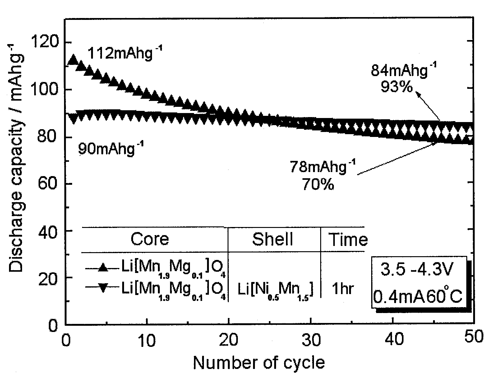
[0080]A battery employing the bilayer cathode active material prepared in Example 1 was evaluated for characteristics using an electrochemical analyzer (Model: Toscat 3000U, Toyo, Japan). In this regard, a charge and discharge experiment was carried out at 30° C. and 60° C. in a potential range from 3.5 to 4.3 V with a current density of 0.2 mA / cm2. A slurry was prepared by mixing the cathode active material powder prepared in Example 1, with the conducting material acetylene black and the binder polyvinylidene fluoride (PVdF) in a weight ratio of 80:10:10. The slurry was uniformly layered on an aluminum foil 20 μm thick, followed by drying at 120° C. in a vacuum. In a well-known process, the cathode thus obtained was separated from a lithium foil counter electrode by a porous polyethylene membrane separator (Celgard 2300, 25 μm thick, Celgard LLC), with a 1 M solution of LiPF6 in a mixture of 1:1 volume of ethylene carbonate and diethyl carbonate se...


PUM


Abstract

Disclosed herein is a layered core-shell cathode active material for secondary lithium batteries, in which the core layer has a structural formula of Li1+a[MxMn1-x]2O4 (M is selected from a group consisting of Ni, Co, Mg, Zn, Ca, Sr, Cu, Zr, P, Fe, Al, Ga, In, Cr, Ge, Sn and combinations thereof, 0.01≦x≦0.25, 0≦a≦0.1) and the shell layer has a structural formula of Li1+a[MyMn1−y]2O4 (M′ is selected from a group consisting of Ni, Mg, Cu, Zn and combinations thereof, 0.01≦y≦0.5, 0≦a≦0.1). In the layered cathode active material, the core layer, corresponding to a 4V spinel-type manganese cathode, functions to increase the capacity of the active material while the shell layer, corresponding to a 5 V spinel-type transition metal mix-based cathode, is electrochemically stable enough to prevent the reaction of the components with electrolytes and the dissolution of transition metals in electrolytes, thereby improving thermal and lifetime characteristics of the active material.

Description

TECHNICAL FIELD[0001]The present invention relates, in general, to secondary lithium batteries and, more particularly, to a layered core-shell cathode active material for secondary lithium batteries.BACKGROUND ART[0002]Since their commercialization by Sony Corporation in 1991, lithium ion secondary batteries have been used as mobile power sources in a broad spectrum of portable electric appliances. With recent great advances in the electronic, communication, and computer industries, high performance electronic and communication products, such as mobile phones, camcorders, laptop PCs, etc., have been developed, partly on the basis of lithium ion secondary batteries being available as power sources therefor. In advanced countries, such as America, Japan, and European countries, furthermore, active research has been conducted into power sources for hybrid automobiles, in which internal combustion engines are combined with lithium ion secondary batteries, particularly secondary lithium ...

Claims


Application Information

Patent Timeline
IPC IPC(8): H01M4/58H01M4/52H01M4/50H01M4/42H01M4/46H01M4/40
CPCC01G45/1242C01G51/54C01G53/54C01P2002/32C01P2002/52C01P2002/72Y02E60/122C01P2004/32C01P2004/61C01P2006/40H01M4/485H01M4/505H01M4/525C01P2004/03Y02E60/10H01M4/48H01M4/04H01M10/0525
Inventor SUN, YANG KOOKLEE, DOO KYUNPARK, SANG HO
Owner SK ENERGY CO LTD (KR)
Learn More