Heavy oil extracted by existing commercially proven in-situ production techniques such as Cyclic Steam Stimulation (CSS) and
Steam Assisted Gravity Drainage (SAGD) are known to have very high operating expenditures (OPEX); significant emissions (CO2, SOx,
NOx, and particulate matter) and
water consumption per
barrel of crude produced; as well as the highest capital expenditure (CAPEX) per flowing
barrel of capacity than all other
oil and gas production in the world.
The aforementioned parameters make the production of heavy oil marginally economical at average long term crude prices while leaving a legacy of ecological damage for future generations.
The current in-situ and mining processes for bitumen are energy intensive in terms of their requirements for steam and power and, unfortunately, produce more emissions (e.g. CO2,
NOx, SOx,
particulates) than any other production technique.
Still further, heavy oil will not separate efficiently at production temperatures using Stokes law, as its
specific gravity is generally too close to that of the
produced water.
The cost of diluents is affected by losses realized in the
separation process and overall blended volume shrinkage as well as transportation costs incurred in transporting the purchased
diluent to site and then transporting it back with the bitumen to the upgrader /
refinery.
In other words, while a highly effective fuel source for bitumen
recovery,
natural gas is a non-ideal and expensive method for the task of simply raising heat to mobilize bitumen.
However, the use of
alternative fuels such as
coal, bitumen, petcoke, vacuum residuals and asphaltenes to reduce OPEX is impeded by the substantial CAPEX increase to install technologies such as gasification and drum boilers (e.g. circulating fluidized beds and direct fired boilers).
Existing in-situ and mining techniques used to extract heavy oil also consume significant amounts of fresh surface and fresh / brackish deep well water per
barrel of production.
The production facilities generally reject water contaminated with concentrated
total dissolved solids (TDS) and
total suspended solids (TSS) from the production process as the additional OPEX and CAPEX makes treating this water for reuse is commercially unfeasible.
This results in the accumulation of large quantities of polluted tailing pond water, typically containing 500 ppm of more of toxic
water soluble hydrocarbons, with long term ecological consequences.
There is also a great deal of water consumed in the reservoir through reservoir losses (i.e. thief zones), voidage replacement (voids created when oil is produced from the reservoir) and from
boiler water blowdown.
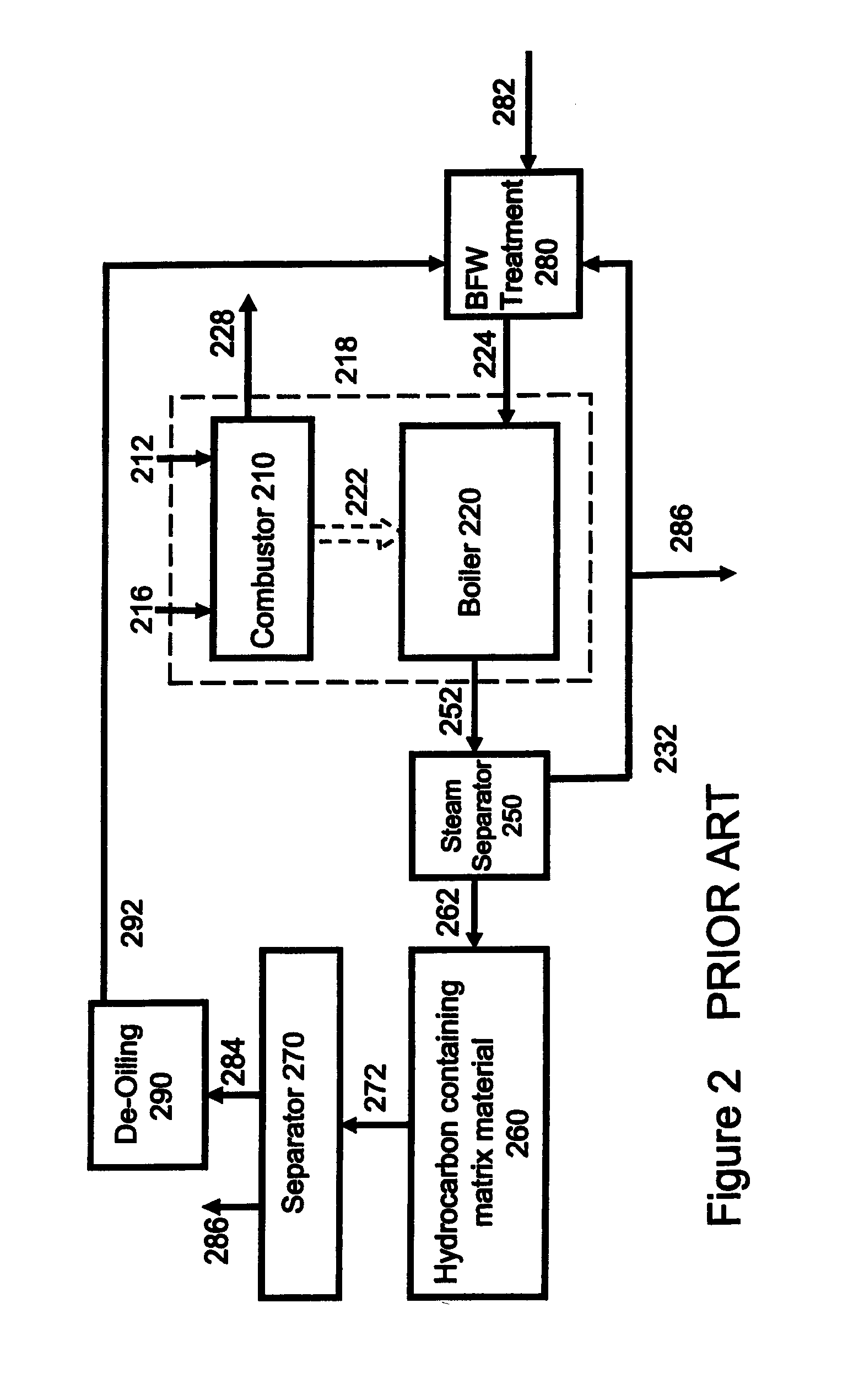
This
system, by using oxidizing air in lieu of
oxygen produced from an
air separation unit, results in a significant increase in the amount of non-condensables in the
high pressure steam and combustion gas mixtures.
This
system, by using oxidizing air in lieu of
oxygen produced from an
air separation unit, results in a significant increase in the amount of non-condensables to steam generated.
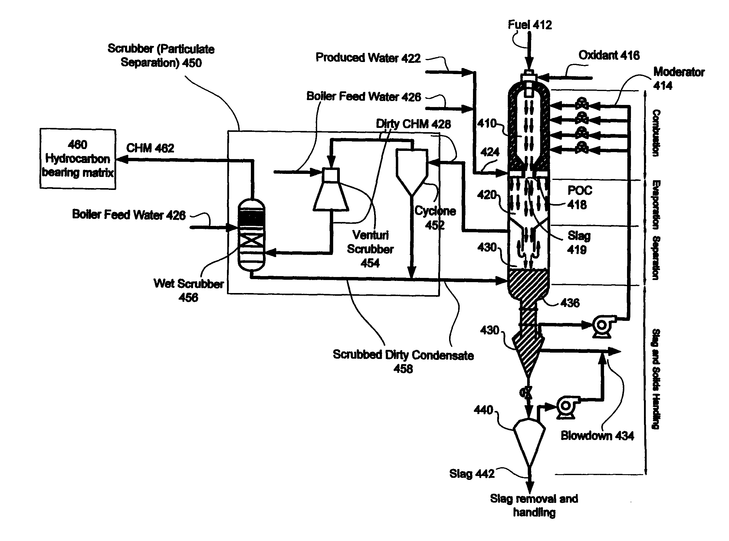
The
combustor and the steam generator are combined into one chamber, and the method allows for high temperature oxy-combustion and simultaneous injection of steam and CO2, However, the
single chamber combustor limits the method's ability to segregate undesirable gases, solids and other products from entering the extraction step which has the potential to interfere with the extraction process or damage the pipes or hydrocarbon-containing formation (e.g.
acid corrosion of
piping from sulphuric / sulphurous acid.
There is no provision for capture of
sulfur and other acid forming gases through direct contact of the
combustion products with water in order to remove them from the
system as a
solid, nor is there provision for recirculation of untreated
produced water for further generation of steam.
This is also no provision for the removal of solids from the walls of the
combustor / steam chamber with a liquid
stream which would tend to cause clogging or performance changes in the system.
This may
restrict the method from the use of many
alternative fuels, especially those containing substantial quantities of inorganic solids.
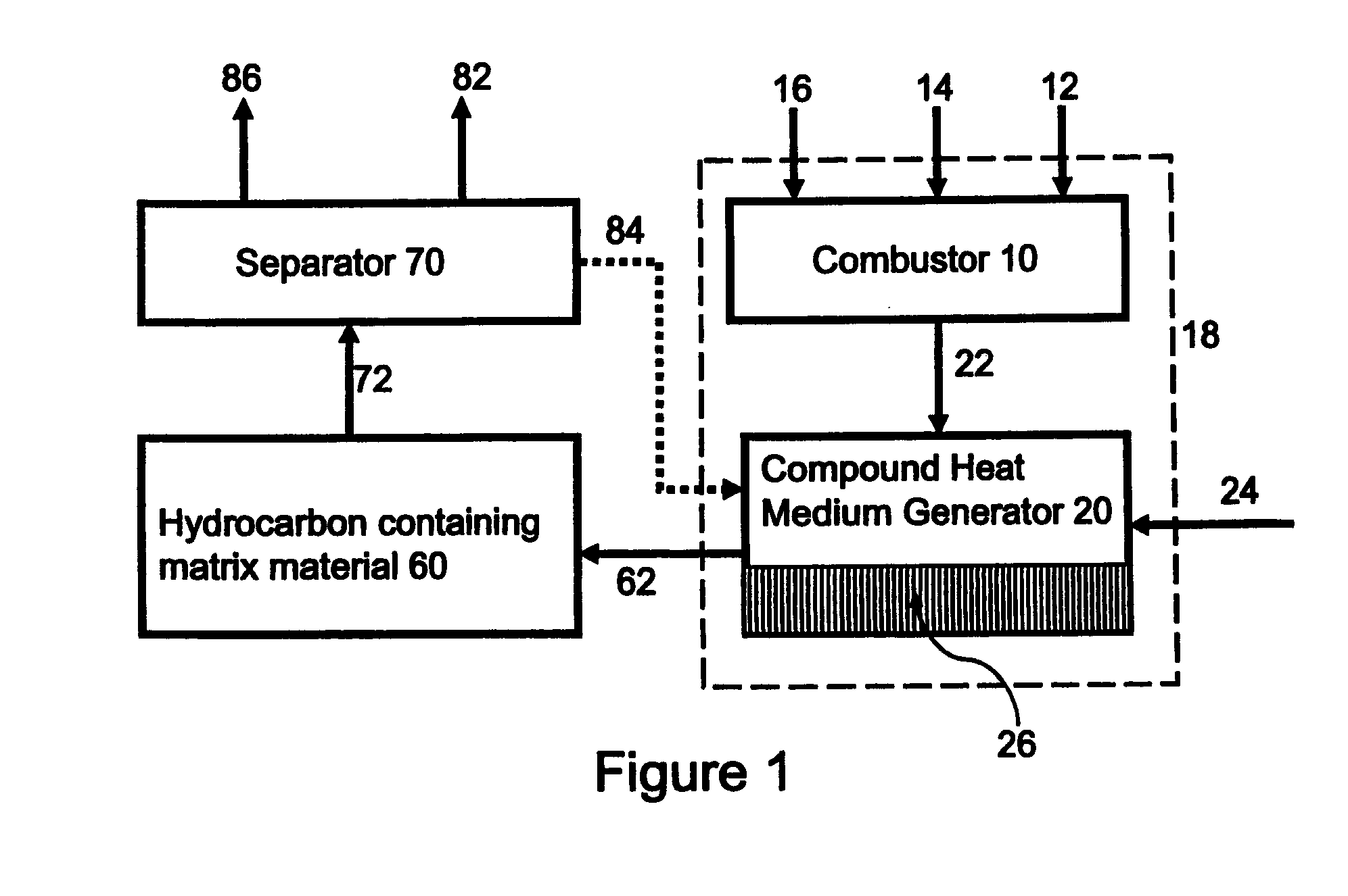
However, the method does not provide for use of
produced water for
steam generation, nor does it discuss the injection of combustion gases along with steam into a hydrocarbon containing matrix or reservoir or the separation and capture of pressurized
carbon dioxide after interaction with the hydrocarbons.
The method is limited to gaseous and liquid fuels because there is no means to
handle the solids.
Special interest groups have and will continue to lobby government / regulatory agencies to stem further development of production facilities in those areas where water is not available or its use for heavy
oil production will result in environmental damage.

