

Structurally Enhanced Cracking Catalysts
a structural enhancement and cracking technology, applied in catalyst activation/preparation, physical/chemical process catalysts, hydrocarbon oil treatment products, etc., can solve the problems of insufficient coke production, particularly undesirable coke and hydrogen products in commercial catalytic cracking processes, and undesirable increases in heat generated, etc., to achieve low fines and stack opacity, improve cracking yield, and reduce the effect of pore volum
- Summary
- Abstract
- Description
- Claims
- Application Information
AI Technical Summary
Benefits of technology
Problems solved by technology
Method used
Image

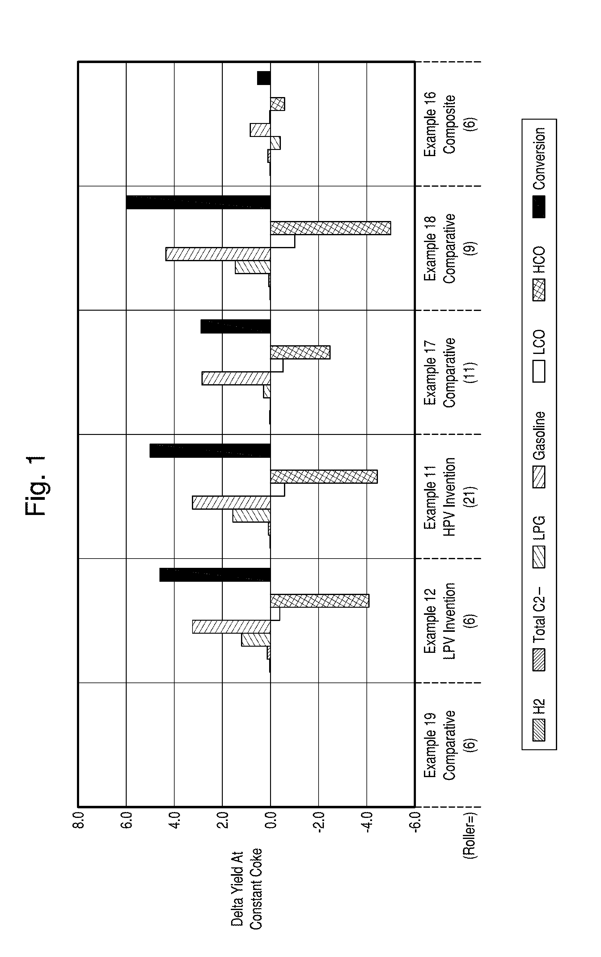
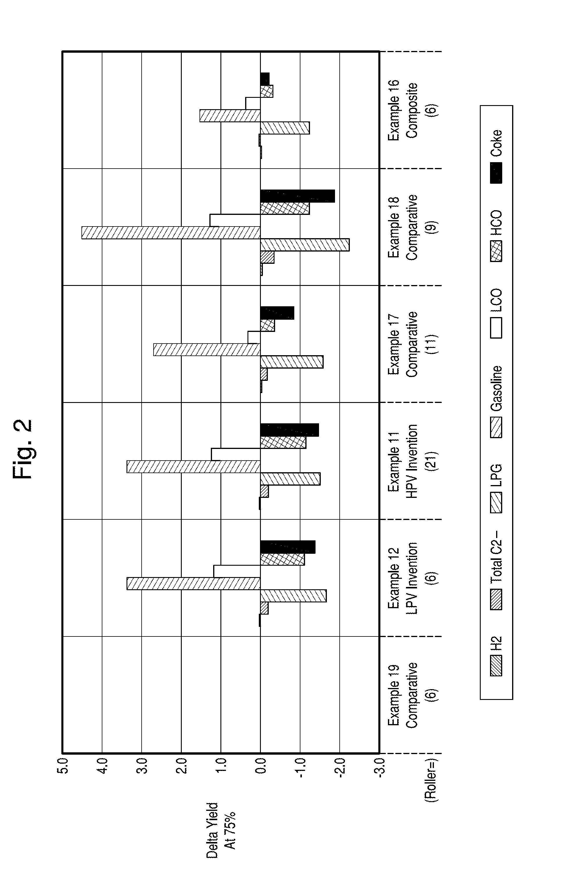
Examples
example 1
Microsphere Precursor of the Invention
[0083]A microsphere was prepared containing 25 parts of LHT hydrous kaolin, 25 parts of Ansilex 93™ spinel-form calcined kaolin, 25 parts of M-93 mullite-form calcined kaolin powder, and 25 parts of mullite-form kaolin core microspheres. To this mixture of hydrous and calcined kaolins was added 2.56 parts of SiO2 added from N-brand™ sodium silicate. The hydrous kaolin source was a 60% solids slurry of LHT, a coarse co-product of the centrifuging of a so-called grey kaolin clay for 90% by weight of particles less than 1 micron in size.
TABLE 1Properties of clay feeds for microspheres of the invention,before and after their individual make-downs.Starting dry kaolin feedsA-93M9-93Dry CoreISP, wt % soldis5052—TBD, g / ml0.390.39—A-93 at 50%M-93 at 50%Feed for spray dryingsolidssolidsDry CoreMullite content123855Microtrac 50%2.952.8544Microtrac 90%15.414.865TBD (on dried clay),0.700.581.1g / mlISP (on dried clay),5249%Not a powderwt % solids
[0084]The Ansi...
example 2
Core / Shell Catalysts with Poor Shell Quality
[0089]Prior to the successful spray drying described in Example 1, multiple attempts had been made using the same composition but different nozzle sizes and atomizer air pressures, in order to obtain an appropriate average particle size. Some of the runs gave finer APS and some of the runs yielded coarser spray dried APS than desired. These off spec runs were combined into a spray drying composite to be used for zeolite crystallization and stability studies, and as an example of poor shell uniformity and morphology, and potentially poor in performance.
[0090]The acid-neutralized microspheres were calcined four hours at 1400° F. in preheated furnace using open cordierite trays during four hours. The product contained 25% mullite by X-ray diffraction, had 8.3% acid solubles, 0.398 cc / gm pore volume in the 40-20,000 angstroms diameter range by mercury porosimetry, a 73 micron APS by Microtrac, and a 0.75 gm / cc ABD.
examples 3-5
Crystallization of Invention Microspheres (Microsphere Precursor of the Invention) and Core / Shell Catalysts with Poor Shell Quality
[0091]The microspheres of Examples 1 and 2 were then crystallized in the laboratory using N-brand sodium silicate using the process described in Examples 4-6 of U.S. Pat. No. 6,656,347 and the seeds of U.S. Pat. No. 4,631,262, incorporated herein by reference. Two crystallizations were run on the Invention of Example 1, the first with no supplemental metakaolin microspheres (MS-2; Example 3) and the second with 7.5% of the microspheres used being MS-2 metakaolin. The use of the MS-2 increases the available amount of limiting reagent reactive alumina, and therefore increases the theoretical stoichiometric yield of NaY zeolite (U.S. Pat. No. 6,656,347). 7.5% of MS-2 was also used in the crystallization of the Example 2 Composite. The crystallization ratios and data for the resulting product are seen in Table 2.
TABLE 2Crystallization of the Invention and of...
PUM
| Property | Measurement | Unit |
|---|---|---|
| diameter | aaaaa | aaaaa |
| contact time | aaaaa | aaaaa |
| contact time | aaaaa | aaaaa |
Abstract
Description
Claims
Application Information