

In-ga-zn-o type sputtering target
a thin film transistor and target technology, applied in the field of sputtering target, can solve the problems of difficult management, significant decrease of the ga content of the thin film, and high specific resistance of the thin film transistor, and achieve low specific resistance, low specific resistance, and high specific resistance.
- Summary
- Abstract
- Description
- Claims
- Application Information
AI Technical Summary
Benefits of technology
Problems solved by technology
Method used
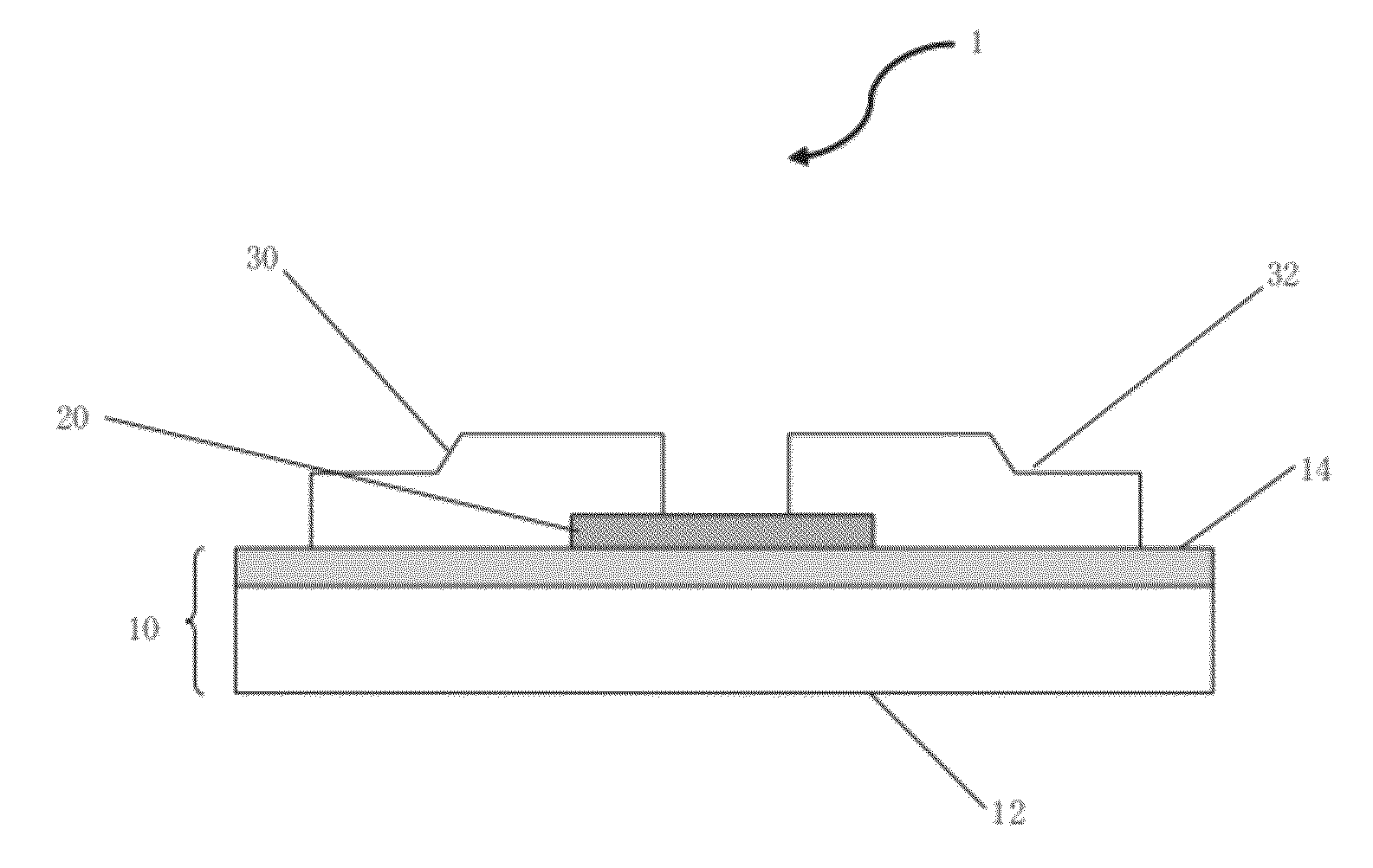
Image

Examples
example 1
(1) Production of a Target
[0153]A target was produced under the following conditions:
(a) Raw Material
[0154]In2O3 Purity 4N, manufactured by Nippon Rare Metal
Ga2O3 Purity 4N, manufactured by Nippon Rare Metal
ZnO Purity 4N, manufactured by Kojundo Chemical Laboratory Co., Ltd.
(b) Mixing: Raw materials were mixed for 24 hours by means of a ball mill.
(c) Granulation: Natural Drying
(d) Shaping:
[0155]Press shaping, surface pressure 400 kgf / cm2, holding for 1 minute
CIP (hydrostatic pressing apparatus), surface pressure 2000 kgf / cm2, holding for 1 minute
(e) Sintering: Electric Furnace
[0156]Heating rate: 1° C. / min
Sintering temperature: 1400° C.
Sintering time: 20 hours
Sintering atmosphere: Air
(f) Post-treatment: No heat treatment was conducted under reduction conditions.
(g) Processing: A sintering body with a thickness of 6 mm was ground and polished to have a thickness of 5 mm.
[0157]The upper and lower surfaces and the lateral edges were cut by means of a diamond cutter. The surface was grou...
example 10
[0192]ZnO powder and Ga2O3 powder were mixed such that the atomic ratio of Zn and Ga became 1:2. The mixture was then pre-fired and pulverized. A shaped body was formed by using these ZnO raw material powder and In2O3 raw material powder. The shaped body contained a crystal form represented by ZnGa2O4 (confirmed by X-ray diffraction). Targets and TFTs were produced and evaluated in the same manner as in Example 1, except that the composition and the conditions were changed to those shown in Table 1-1. The results are shown in Table 1-1.
[0193]Charts obtained by subjecting the surface of the targets obtained in Examples 2, 3 and 6 to X-ray diffraction (Cukα rays) are shown in FIGS. 9 to 11.
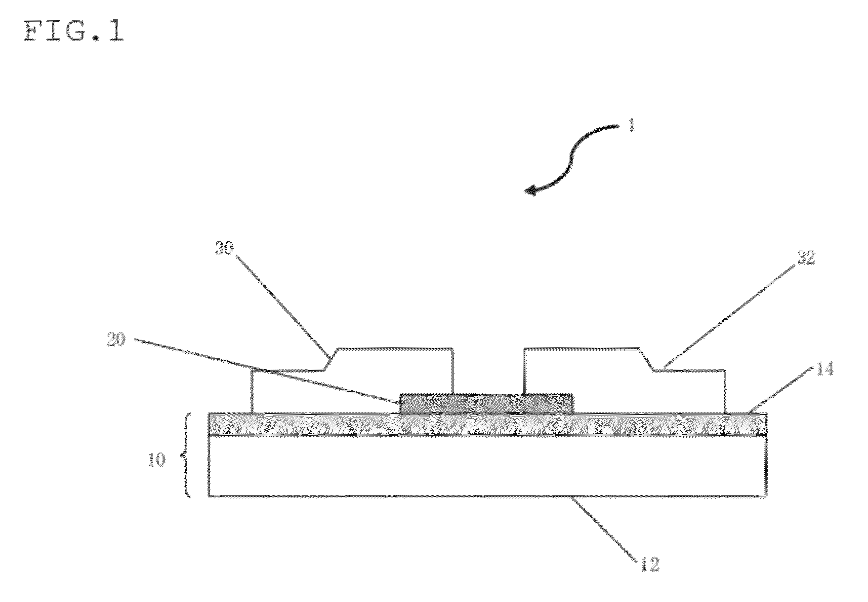
[0194]Microscopic photographs of the dispersion map taken by means of an EPMA of In, Ga, Zn and O of the sintered oxide body prepared in Example 1 and 2 are shown in FIG. 12 and FIG. 13. Microscopic photographs taken by means of an EPMA of the oxide sintered body prepared in Example 4 was shown in F...
PUM
| Property | Measurement | Unit |
|---|---|---|
| Length | aaaaa | aaaaa |
| Length | aaaaa | aaaaa |
| Ratio | aaaaa | aaaaa |
Abstract
Description
Claims
Application Information