
Multispectral therapeutic light source

a multi-spectral, light source technology, applied in the field of multi-spectral light sources, can solve the problems of insufficient use of practical exposure time, inconvenient manufacturing, and inability to meet the needs of patients, and achieve the effects of reducing surface heating, reducing cost and cost, and efficient output photon flux

Active Publication Date: 2014-09-25
JONES GARY W
View PDF11 Cites 88 Cited by
  • Summary
  • Abstract
  • Description
  • Claims
  • Application Information

AI Technical Summary

Benefits of technology

This patent describes a new light source device that can provide high-quality, cost-effective output over a wide range of wavelengths. It aims to improve the efficiency of transmitting light into surfaces being illuminated, with lower heating and better energy efficiency. The device can be used in several applications, including photodynamic therapy and low level light therapy. It has the potential to exceed the intensity of current commercial technologies and can be scaled up for larger areas of light exposure.

Problems solved by technology

Conventional light therapy methods covering wavelengths within the ONIR spectral ranges compromise important parameters excessively to the point where few are effective using practical exposure times, or are very expensive.
Light spectrum and intensity output with some similarity to those provided by the invention described herein can be obtained by other types of light sources: (1) using mixtures of multiple different color LEDs and / or laser diodes, but this can be expensive and more complicated to manufacture at low cost for large area light sources, and (2) by filtering out light at some wavelengths of light from broad-spectrum light sources such as gas discharge lamps, fluorescent, or halogen lamps but these techniques are also expensive, generate excessive heat, and waste energy when applied to large area high intensity lighting applications.
Currently available light spectrum spectral conversion or shifting technologies provide relatively low overall light spectrum conversion efficiency and / or costly conversion of 360 nm-650 nm spectral range input light into the ONIR spectral range above 650 nm.
Many current light therapy sources also only provide light in small portions of the ONIR spectral range, generate excessive amounts of heat, require high input power and poor energy efficiency, provide low efficiency light transmission into the tissue, are not sufficiently photostable, and costly in systems that can provide deep penetrating near-IR light at high intensities (even over 50 mW / cm2).
Higher concentrations of phosphor particles or a larger volume phosphor matrix is needed for over 80% light conversion to the phosphor's spectral emission range, but this can reduce the external QY efficiency by another 30%.
Near IR phosphors have been shown, but few good choices are available commercially at this time.
Organic dyes in polymer matrices that exhibit high quantum yield in the over 90% range for ONIR light have generally not been seriously considered sufficiently stable for high luminance light sources, have only recently become commercially available, and / or have poor extinction coefficients in the desired light absorption spectral ranges so they require large quantities of dye when >90% of the incoming light is to be converted into the ONIR spectral range.
Conversion of violet or blue light to ONIR light using most organic dyes requires a large stokes shift or multiple stacked dyes, resulting in poor photostability, added complexity, high cost, and poor energy efficiency.
Fluorescent dyes are typically not used in LEDs as it has been non-obvious how to accomplish this using available dyes in reasonable medium, photostability issues, and the stokes shift is usually small so most red emitters tend to absorb poorly in the violet-blue.
Non-fluorescent dyes are sometimes used as filters to absorb portions of the light spectrum to provide more pure visual color, but absorption filtering wastes a significant amount of light and is usually undesirable for our applications unless it is to block UV or long wavelength IR.
Most ONIR range photoluminescent materials are very expensive per gram of dye, not very high quantum yield, and / or provide poor stability in use.
Unfortunately, minimal heat producing, high intensity light source applications for light therapy, as an example, do require all the parameters to be simultaneously met.
Considerable light is lost in many systems just due to unrecovered skin reflection losses.
Almost no practical products available to consumers or clinics provide the total absorbed light dose necessary for treatment over 4 cm deep in tissue and / or through living bone in an under 30 minute exposure time per location, and those that do provide high intensity light are typically expensive and require high power lamps and / or extensive heat control capabilities.
However, for deep tissue light treatments without the use of skin-penetrating probes, the light scattering effects for small area sources reduce the effective light intensity at large depths through tissue significantly.
Of the light that is actually incident on the tissue surface, up to 50% or more of the incident light is reflected off of and / or backscattered out of the tissue and is lost for therapeutic purposes in most commercial system designs.
This is due to high scattering and absorption losses even for the best penetrating near-IR light, even with large area light sources that effectively reduce some of the scattering losses.
This can be very difficult to practically accomplish using typical under 10 Watt lamp power consumer handheld or small mounted systems unless strapped to the body for long periods of time.
Without the light source shaped to the body, reflection and backscatter light loses cannot be minimized.
At the desired high light intensities and treatment duration times desired for deep-though-tissue or into-bone treatments, heating of the tissue surface can becomes a major issue for conformal light sources.
Heating of tissue surfaces in conformal systems held against the tissue surface and cost of high efficiency light emitting devices at the desired wavelengths has forced compromises that result in many LLLT products on the market to be largely ineffective and caused most PDT products to be higher cost than desirable.
Compromises in current products have included: (1) too low effective light intensity, (2) non-optimal light spectra or incomplete complement of wavelengths, (3) inability to achieve deep-in-tissue light doses in practical time periods, (4) poor therapeutic light transmission deep into tissue, and (5) overheating of tissue surface discomfort.
Conformal light sources in near-direct contact with the target tissue and that reflect reflected light back to the tissue to be illuminated can best efficiently direct light into tissue, although available systems do this poorly.

Method used


Image

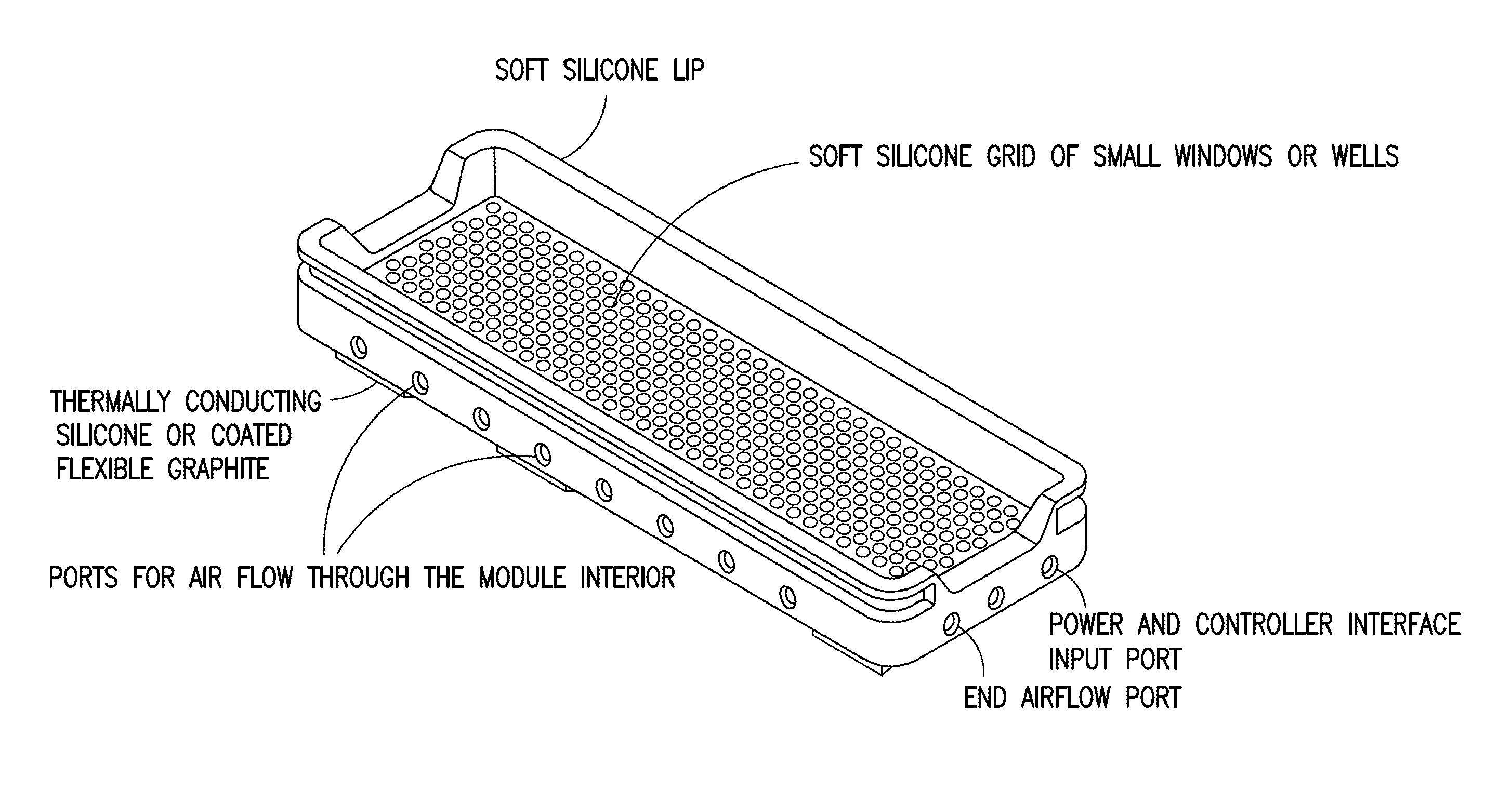
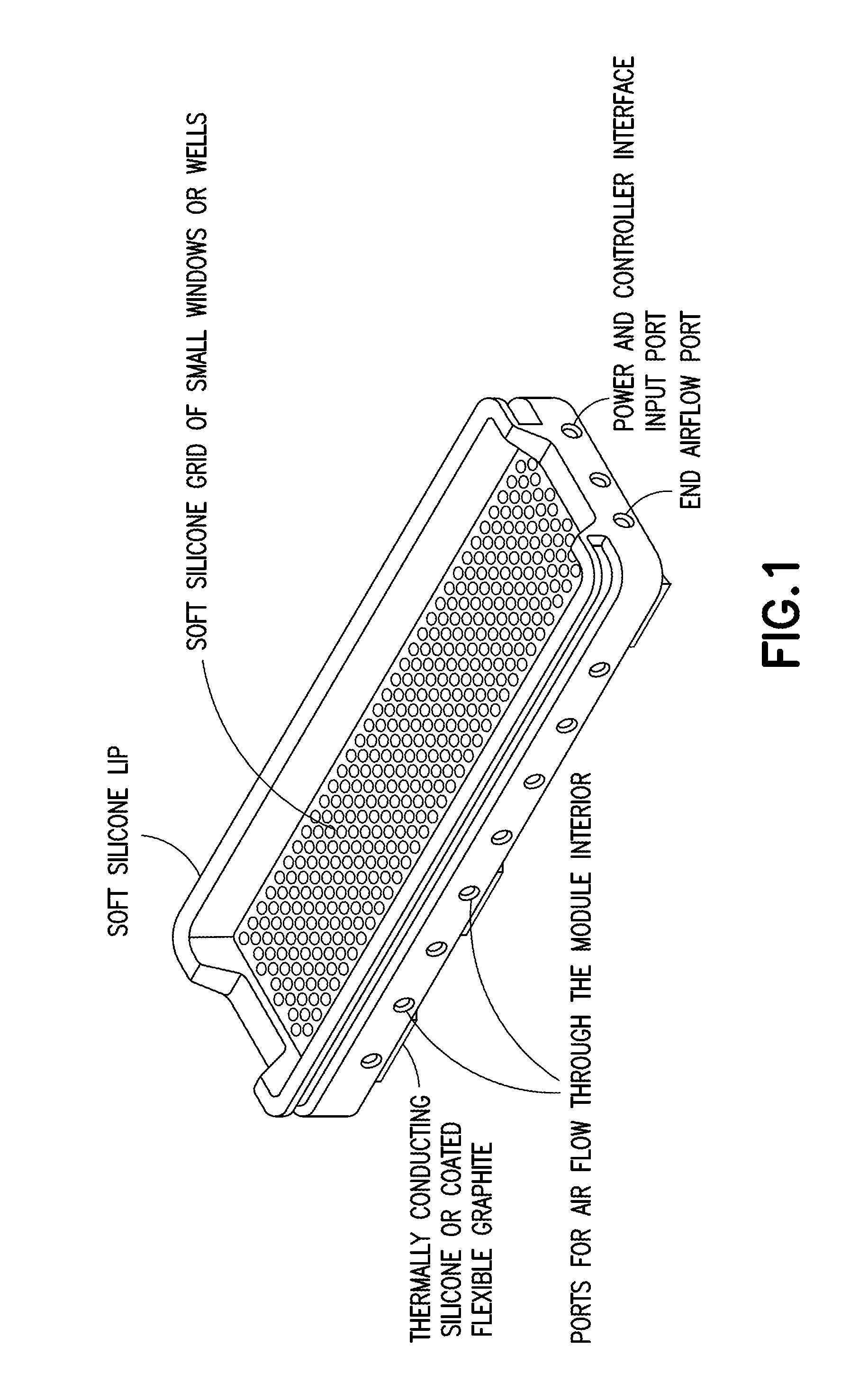
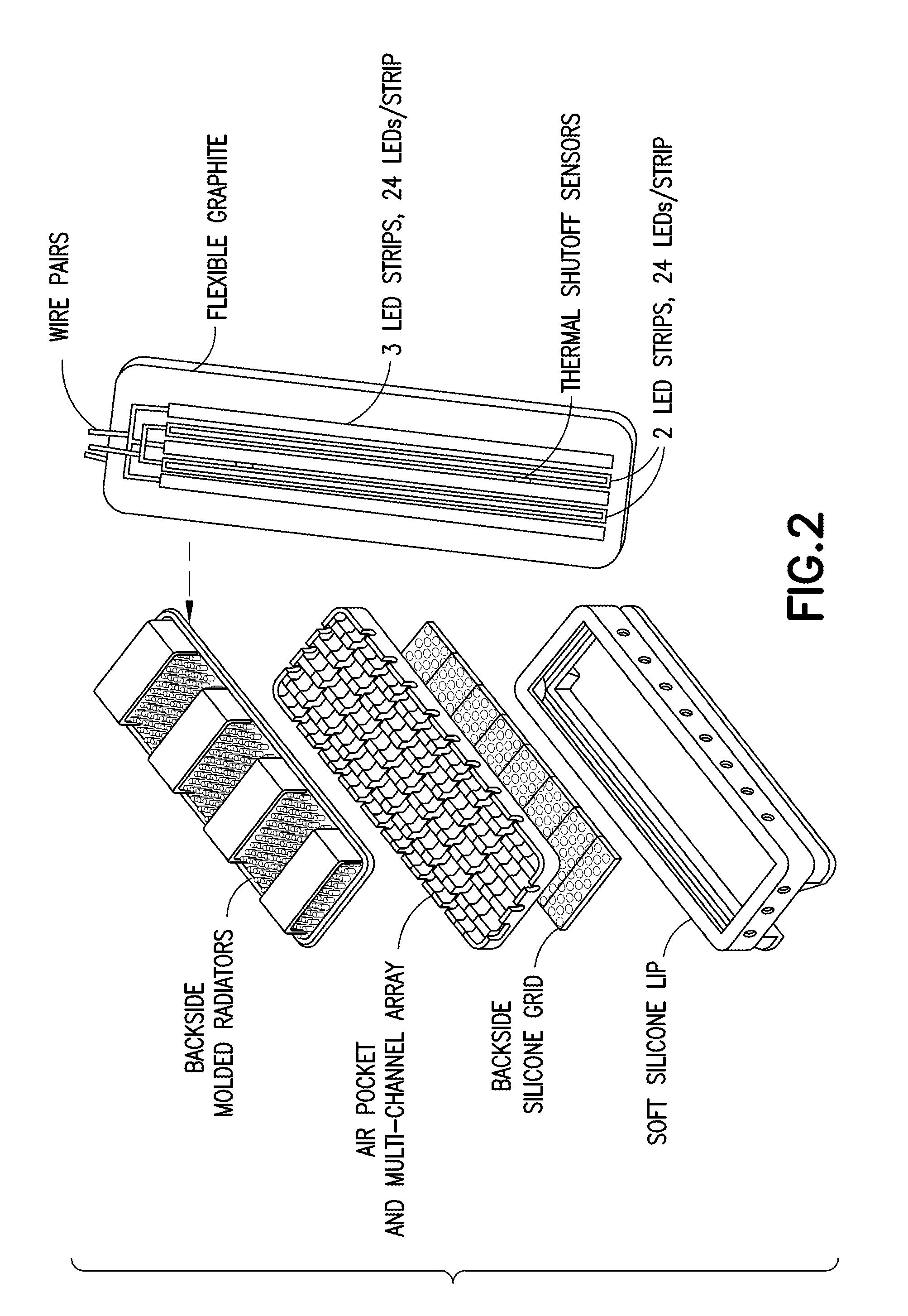
  • Multispectral therapeutic light source
  • Multispectral therapeutic light source
  • Multispectral therapeutic light source

Examples


embodiment 1

[0151]Referring now to specific Embodiment 1, there is provided a light source, comprising an array of two or more LEDs and / or OLS, where at least one of the LEDs and / or OLS has one or more materials containing photoluminescent phosphor(s), dye(s), and / or OCSTs that spectrum-shift most of the light energy emitted from the selected LEDs and / or OLS into an emission spectrum substantially within the ONIR wavelength range. Different spectrum-converting materials may be mixed or sequentially placed in the light path so that 1, 2, or more different spectrum converters are present in the light path of at least half the collective initial LED light output.

[0152]Still referring to Embodiment 1, the spectrum converter can be a phosphor or quantum dots mixed into clear silicone or other matrix material placed in the proximity of, or touching the LED light-output surface at a concentration, thickness, and area that can convert 50% or more of initial LED light into broad spectrum ONIR light with...

embodiment 2

[0155]A specific example, designated as Embodiment 2, has an additional light conversion material placed in all or part of the light path, consisting of one or more over 60% quantum yield dyes in an inorganic or polymer matrix such as polycarbonate, impact resistant acrylic, or PVC. Polymer matrix mixtures are anticipated and can be beneficial. For most preferred embodiments 0.05-5 mm would an optimal range.

[0156]Selected perylene derivative dyes have much higher photostability, higher QY, and ease of integration into a wide range of light converters than almost any other red or near-IR spectral range organic dyes. Even though photostability is lower than phosphors, this can be managed in many medical applications for the life of many products or the conversion material can be changed out as part of routine maintenance. The absorption and emission characteristics are needed for useful ONIR spectrum.

[0157]The present invention incorporates inclusion of two new perylene derivative pho...

embodiment 3

[0162]the spectrum converter is comprised of a light source consisting of an array of two or more LEDs with principal light output in the 390-490 nm range, where at least one of these LEDs is covered by one or more layers closest to the LED containing photoluminescent phosphor(s) and / or quantum dots so that over 50% of the output light spectrum from the converted LED(s) is within the ONIR spectral range. Additional spectrum-converting layer(s) using fluorescent dye(s) or quantum dots then converts most of the of the light energy exiting the first layer(s) into the ONIR spectral range, and / or into a longer wavelength portion of the ONIR spectral range. This device's output light from the spectrum converter(s) may intentionally contain up to 40% light in the violet and / or blue spectral range with >60% light in the ONIR spectral range. Light source designs with over 99% of the photons in the ONIR range are achievable with this structure and appropriate photoluminescent material concent...


PUM


Abstract

A light source apparatus including light spectrum-converting materials that emit light primarily over large portions of the 360 nm-480 nm and the 590-860 nm spectral range is provided. This apparatus provides a cooled, high-luminance, high-efficiency light source that can provide a broader spectrum of light within these spectral ranges than has been cost-practical by using many different dominant peak emission LEDs. Up to 15% of the output radiant power may be in the spectral range 350-480 nm in one embodiment of this device, unless a specific separate source and lamp operating mode is provided for the violet and UV. Control methods for light exposure dose based on monitoring and controlling reflected or backscattered light from the illuminated surface and new heat management methods are also provided. This flexible or rigid light source may be designed into a wide range of sizes or shapes that can be adjusted to fit over or around portions of the bodies of humans or animals being treated, or mounted in such a way as to provide the special spectrum light to other materials or biological processes. This new light source can be designed to provide a cost-effective therapeutic light source for photodynamic therapy, intense pulsed light, for low light level therapy, diagnostics, medical and other biological applications as well as certain non-organic applications.

Description

CROSS-REFERENCE TO RELATED APPLICATION[0001]The benefit of U.S. Provisional Patent Application No. 61 / 802,234 filed Mar. 15, 2014 in the names of Gary W. Jones for “MULTISPECTRAL LIGHT SOURCE” is hereby claimed under the provisions of 35 USC 119. The disclosure of U.S. Provisional Patent Application No. 61 / 801,602 is hereby incorporated herein by reference in its entirety, for all purposes.FIELD[0002]The present disclosure relates to a multispectral light source having utility for light therapy and other applications.DESCRIPTION OF THE RELATED ART[0003]Light therapy devices and methodologies that have been publicly reported or claimed include (1) Low level light therapy (LLLT) for the treatment of inflammation and / or for tissue surface, other tissue healing, skin and tissue rejuvenation, muscle growth enhancement, muscle repair and pain reduction, accelerated tendon healing, joint or cartilage treatments, plantar fasciitis, pain management, traumatic brain injury (TBI) damage risk r...

Claims


Application Information

Patent Timeline
Patent Type & Authority Applications(United States)
IPC IPC(8): A61N5/06A61N2/00
CPCA61N5/06A61N2/002A61N2005/0632A61N2005/0652A61N2005/0626A61N5/0616A61N5/0624A61N2005/005A61N1/0456A61N1/0452
Inventor JONES, GARY W.
Owner JONES GARY W
Learn More