Erosion And Corrosion Resistant Protective Coatings For Turbomachinery

a protective coating and corrosion resistance technology, applied in the direction of machines/engines, mechanical equipment, superimposed coating process, etc., can solve the problems of delamination, debonding and delamination of the blade's composite skin, wear, delamination of the rotor blade components, etc., to achieve high flexibility, anti-icing, erosion and corrosion resistance properties, and anti-icing properties. high

Inactive Publication Date: 2017-02-02
NANO PROD ENG
View PDF7 Cites 20 Cited by
  • Summary
  • Abstract
  • Description
  • Claims
  • Application Information

AI Technical Summary

Benefits of technology

[0012]A hard wearing ceramic surface provides high flexibility when the coating thickness exceeds 5 μm yet, has high erosion and corrosion resistance properties as well as anti-icing properties and high reflectivity of the sun's radiation. The coating has either monolithic or multilayer architecture consisting of alternating metal layers and ceramic layers. Sublayer thickness and coarseness vary among the layers across the multiple layers so the coating remains flexible against the thin metal substrate that is a sheath for protecting helicopter rotorblades or airfoil yet presents a tough outer surface that is resistant to erosion and corrosion.

Problems solved by technology

The rotorblades of modern helicopters are made of composite materials and suffer from wear due to sand and rain erosion as well as overheating by absorbing the sun's infrared rays.
Wear degrades the adhesive used in these laminated composites and results in debonding and delaminating the blade's composite skin.
Specifically, the high temperatures resulting from the blade absorbing the sun's infrared rays cause bonding deterioration and delamination of helicopter rotor blade components.
In addition to the ultraviolet effects of the sun, erosion, poor repairs and repeated high cyclical loading exasperates the problems of wear causing minute openings in the rotorblade's skin.
This invention, while helping to protect the rotor blade against overheating, does not help in preventing deterioration due to sand and rain erosion.
While this invention improves the bonding between the abrasion strip and the blade, it does not help to substantially improve the erosion resistance of the strip which will result in the necessity of replacing the strip too often especially when helicopters operate in harsh environments.
The vapor deposition of Schroeder is conducted at relatively low temperature, thus the substrate will have lost little of its initial high strength properties, however, the requirement of low surface roughness of the deposited layer is not addressed by U.S. Pat. No. 5,152,774.
Unfortunately these coatings are too thin for application as a protective erosion and corrosion resistive coatings for protective shields of the helicopter rotor blades.
In addition these coatings do not have high enough reflectivity to reduce the heat ingested from sun's radiation.
Any post-deposition heat treatment which may be required to maintain corrosion resistance of the substrate, may lead to internal stresses in the coating due to differences in the grain size, and can eventually lead to abrasion, spalling, crack formation, grain separation, surface fractures, uneven edges and rough surfaces, and the like, which can drastically reduce the wear resistance and durability of coated objects.
None of the above discussed methods are concerned with even grain size and surface structure, and low micro-roughness of the vapor deposited hard, ceramic coatings.
Another disadvantage of the above mentioned conventional PVD and CVD technologies is that they are producing the hard, but brittle coatings which have very limited ductility, unable for bending without developing a large cracks, fracturing and delaminations.
This makes these coatings non-applicable for such applications as protective shields for the helicopter rotor blades made of thin metal sheets or foils.
Thermal spray methods are producing large surface roughness as well as voids and porosity in coating layers detrimental to erosion and corrosion protection, while PVD and CVD methods are known to produce denser coatings having smoother surfaces.
Cathodic arc deposition process produces large flux of metal vapor plasma featuring metal ions with energies exceeding 40 eV for most of the metal targets, but as a drawback it also generates large amount of microparticles having diameters ranging from nanoparticles to more than 10 μm.
These processes require high substrate temperatures, typically above 900 deg C., resulting in a dramatic increase of surface roughness by thermal surface grooving.
The disadvantage of this type of coating is its limited thickness range, which makes it non-applicable as erosion and corrosion resistive coatings for the protective shields of helicopter rotor blades.

Method used


Image

  • Erosion And Corrosion Resistant Protective Coatings For Turbomachinery
  • Erosion And Corrosion Resistant Protective Coatings For Turbomachinery
  • Erosion And Corrosion Resistant Protective Coatings For Turbomachinery

Examples


example 1

Large Area Filtered Arc Deposition (LAFAD) of Erosion and Corrosion Resistant TiAlN Multilayer Multi-Segment Coating on Metal Sheets, Foils, Instruments and Machine Components

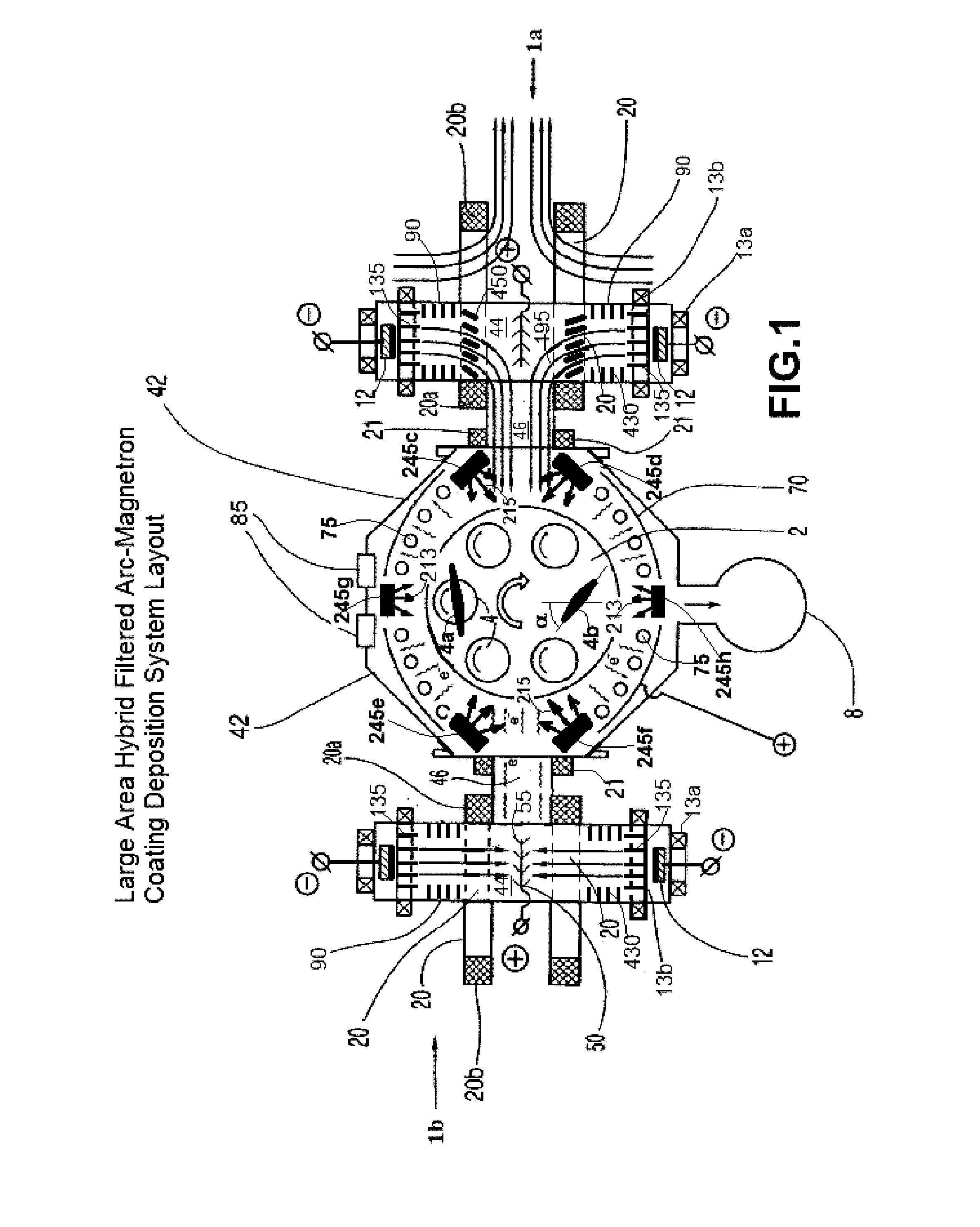
[0078]The arc coating apparatus shown in FIG. 1 is used in this process. The apparatus is equipped with two dual-filtered arc sources, 1a and 1b having round primary cathode targets 12 measuring 3″ in diameter and 2″ in height, one filtered arc source 1a having at least one titanium target, preferably two titanium targets, and the other 1b having at least one aluminum target, preferably two aluminum targets. The filtered arc sources 1a and 1b can operate in magnetic shutter mode: When the deflection magnetic system (magnetic deflection and focusing coils 20 and 21) is activated in magnetic shutter open mode, the metal vapor plasma generated by the cathode targets 12 is transported toward coating chamber 42 to provide metal or metal-ceramic coatings on substrates to be coated 4. When the deflecting magnetic syst...

example 2

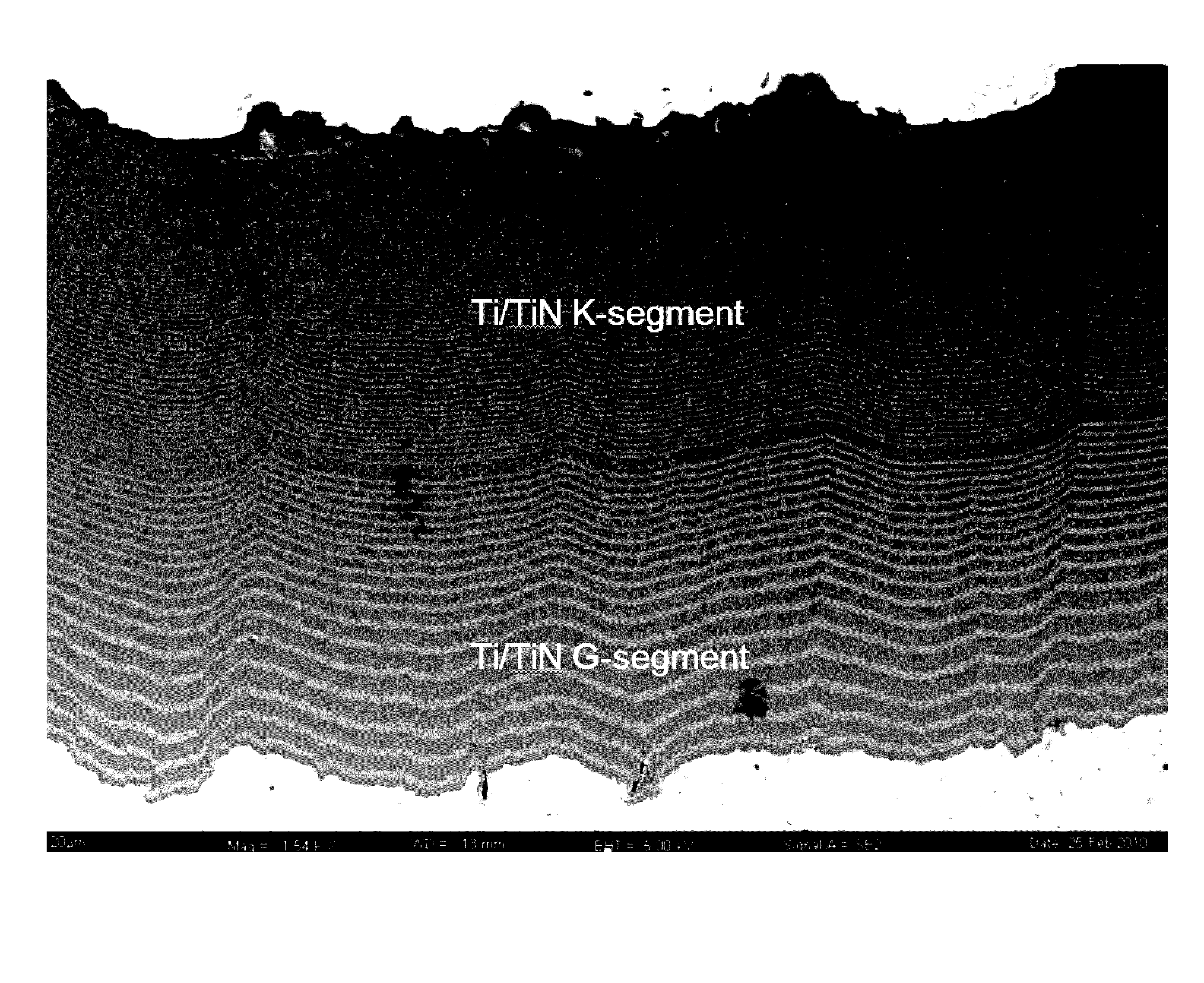
Deposition of a 2-Segment Micro-Nano-Laminated Ti / TiN Coating by LAFAD Process

[0081]A Ti / TiN micro-nano-laminated coating was deposited by an LAFAD process on 1″×1″×⅛″ square coupons made of Ti6Al4V alloy. The LAFAD process used in Example 2 is modified version of the process used in Example 1. For example, Example 2 utilizes titanium targets in both primary arc sources while Example 1 had titanium targets in one primary arc source and aluminum targets in the other primary arc source. The coupons 4 were pre-treated by wet blasting prior to being loading into coating chamber 42 of the coating system shown in FIG. 1. Only one unidirectional dual LAFAD source 1a was used in this process. Both primary cathodic arc sources of the LAFAD source 1a were equipped with titanium targets. Substrate coupons 4 were installed on turntable 2 rotating about a single rotation axis at a rotating speed of 12 RPM. In single-rotation (SR) mode, the substrates are rotated around the axis of the turntable ...

example 3

Deposition of TiN Erosion and Corrosion Resistant Coating on Airfoils by Hybrid Filtered Cathodic Arc-Magnetron Sputtering Deposition Process

[0084]In this example, the TiN coating of monolithic coating architecture is applied by hybrid filtered cathodic arc-magnetron sputtering deposition technology for deposition of erosion and corrosion resistant coatings on airfoils of turbine engine. As in Example 2, the coating system shown schematically in FIG. 1 is used for this coating deposition process. The airfoils were installed at turntable 2, for example at the 60° to the radius as shown in airfoil samples 4b, or with double rotation as shown in airfoil sample 4a in FIG. 1. In double rotation, airfoil sample 4a further undergoes rotation about a longitudinal axis of airfoil sample 4a, which is parallel to the rotation axis of turntable 2. All primary cathodic arc sources of the filtered cathodic arc sources 1a and 1b are equipped with cathode targets 12 made of titanium. All targets of...


PUM

PropertyMeasurementUnit
thicknessaaaaaaaaaa
Raaaaaaaaaaa
Raaaaaaaaaaa

Abstract

An erosion and corrosion resistant protective coating for turbomachinery application includes at least one ceramic or metal-ceramic coating segment deposited on surface of a conductive metal substrate subjected to a pre-deposition treatment by at least blasting to provide the surface with texture. The erosion and corrosion resistant coating has a plurality of dome-like structures with dome width between in range from about 0.01 μm to about 30 μm. The at least one coating segment is formed by condensation of ion bombardment from a metal-gaseous plasma flow, wherein, at least during deposition of first micron of the coating segment, deposition rate of metal ions is at least 3 μm/hr and kinetic energy of deposited metal ions exceeds 5 eV.

Description

CROSS-REFERENCE TO RELATED APPLICATIONS[0001]This application is a continuation-in-part of U.S. patent application Ser. No. 12 / 790,691 filed May 28, 2010, which is incorporated herein by reference in its entirety.FIELD OF THE INVENTION[0002]The present invention relates to coated metal sheets to protect against abrasion and erosion wear, corrosion, high temperature oxidation, and other types of surface born degradation, and also relates to the method of making the protective coatings on metal sheets and various applications of metal sheets with protective coatings, and more particularly for protection of turbomachinery components such as covers for helicopter rotors and airfoils for turbine engines.BACKGROUND OF THE INVENTION[0003]The rotorblades of modern helicopters are made of composite materials and suffer from wear due to sand and rain erosion as well as overheating by absorbing the sun's infrared rays. Wear degrades the adhesive used in these laminated composites and results i...

Claims


Application Information

Patent Timeline
Patent Type & Authority Applications(United States)
IPC IPC(8): F01D5/28F01D25/00C23C14/32C23C14/35C23C14/02C23C14/06
CPCF01D5/288C23C14/028C23C14/0688F05D2300/611C23C14/35F01D25/005C23C14/325C23C28/322C23C28/34C23C28/343C23C28/44F05D2250/28C23C24/04C23C28/321C23C28/3215C23C28/341C23C28/345C23C28/3455F05D2300/22F05D2230/312F05D2300/2284F01D25/007Y02T50/60C23C28/36
Inventor GOROKHOVSKY, VLADIMIR
Owner NANO PROD ENG
Why Eureka
Try Eureka