Polymer nanocomposite implants with enhanced transparency and mechanical properties for administration within humans or animals

a technology of nanocomposite implants and nanocomposites, which is applied in the field of nanoscale powders, can solve the problems of difficult fabrication of such composites, large number of suitable filler materials, and limited range of low-cost pure phase materials

Inactive Publication Date: 2005-02-15
PPG IND OHIO INC
View PDF12 Cites 140 Cited by
  • Summary
  • Abstract
  • Description
  • Claims
  • Application Information

AI Technical Summary

Benefits of technology

As used herein, a “nanostructured powder” is one having a domain size of less than 100 nm, or alternatively, having a domain size sufficiently small that a selected material property is substantially different from that of a micron-scale powder, due to size confinement effects (e.g., the property may differ by 20% or more from the analogous property of the micron-scale material). Nanostructured powders often advantageously have sizes as small as 50 nm, 30 nm, or even smaller. Nanostructured powders may also be referred to as “nanopowders” or “nanofillers.” A nanostructured composite is a composite comprising a nanostructured phase dispersed in a matrix.

Problems solved by technology

However, low cost pure phase materials are somewhat limited in the achievable ranges of a number of properties, including, for example, electrical conductivity, magnetic permeability, dielectric constant, and thermal conductivity.
The number of suitable filler materials for composites is large, but still limited.
In particular, difficulties in fabrication of such composites often arise due to issues of interface stability between the filler and the matrix, and because of the difficulty of orienting and homogenizing filler material in the matrix.
Some desirable properties of the matrix (e.g., rheology) may also be lost when certain fillers are added, particularly at the high loads required by many applications.

Method used


Image

  • Polymer nanocomposite implants with enhanced transparency and mechanical properties for administration within humans or animals
  • Polymer nanocomposite implants with enhanced transparency and mechanical properties for administration within humans or animals
  • Polymer nanocomposite implants with enhanced transparency and mechanical properties for administration within humans or animals

Examples


example 1

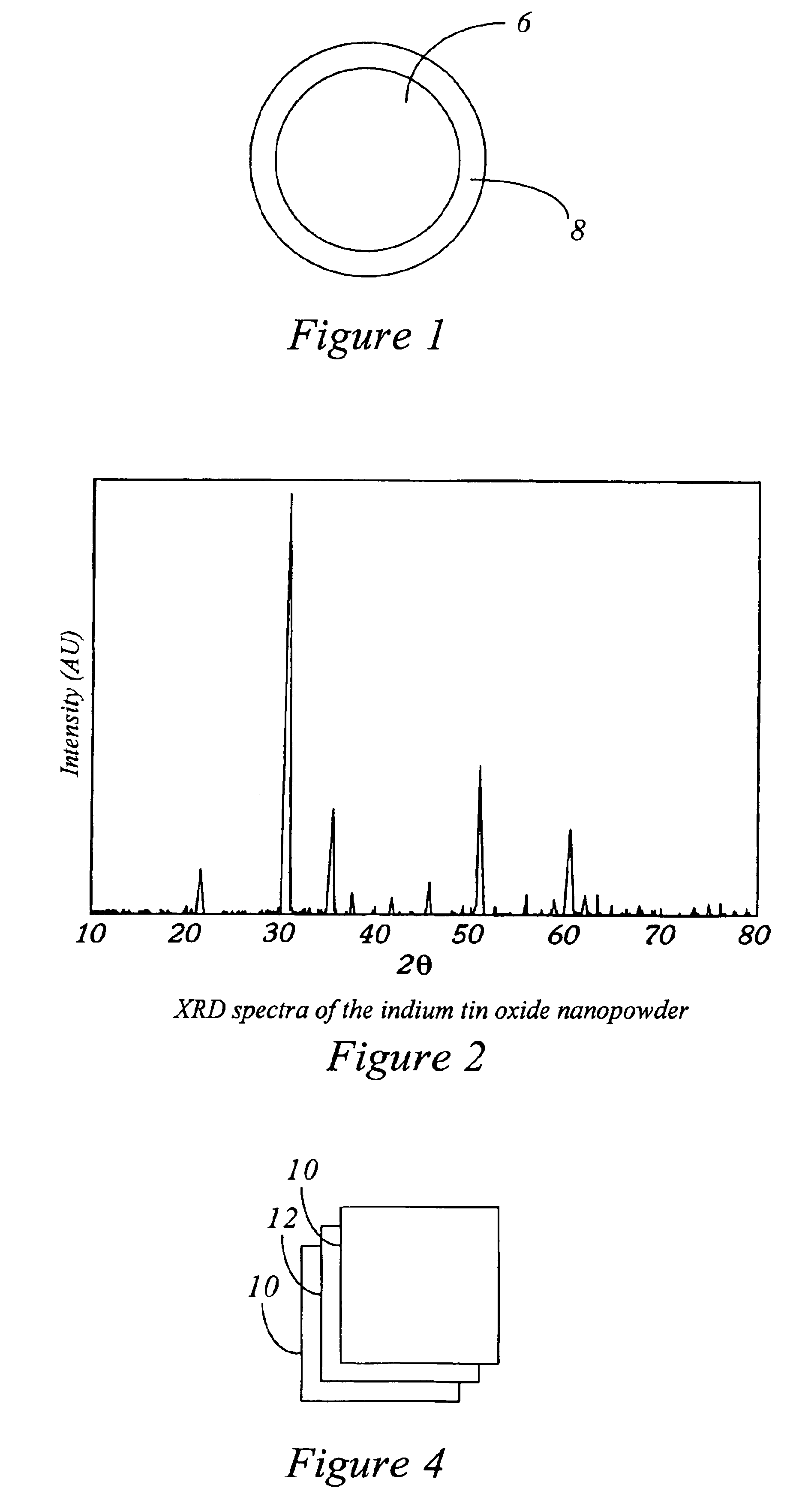
Indium Tin Oxide fillers in PMMA

A stoichiometric (90 wt % In203 in SnO2) indium tin oxide (ITO) nanopowder was produced using the methods of copending patent application Ser. No. 09 / 046,465. 50 g of indium shot was placed in 300 ml of glacial acetic acid and 10 ml of nitric acid. The combination, in a 1000 ml Erlenmeyer flask, was heated to reflux while stirring for 24 hours. At this point, 50 ml of HNO3 was added, and the mixture was heated and stirred overnight. The solution so produced was clear, with all of the indium metal dissolved into the solution, and had a total final volume of 318 ml. An equal volume (318 mL) of 1-octanol was added to the solution along with 600 mL ethyl alcohol in a 1000 mL HDPE bottle, and the resulting mixture was vigorously shaken. 11.25 ml of tetrabutyltin was then stirred into the solution to produce a clear indium / tin emulsion. When the resulting emulsion was burned in air, it produced a brilliant violet flame. A yellow nanopowder residue was colle...

example 2

Hafnium Carbide Fillers in PMMA

Nanoscale hafnium carbide fillers were prepared as described in copending U.S. patent application Ser. Nos. 08 / 706,819 and 08 / 707,341. The nanopowder surface area was 53.5 m2 / gm, and mean grain size was 16 nm. Micron scale hafnium carbide powder was purchased from Cerac (catalog number H-1004) for comparison.

Composite pellets were produced as described in Example 1, by mixing filler and polymer with a mortar and pestle and pressing in a hydraulic press. Pellets were produced containing either nanoscale or micron scale powder at three loadings: 20 vol % powder, 50 vol % powder, and 80 vol % powder. The pellets were electroded as described above, and their resistivities were measured. (Because of the high resistances at the 20% loading, these pellets' resistivities were measured at 100V. The other pellets were measured at IV, as described in Example 1).

Results of these resistivity measurements are summarized in Table 1. As can be seen, the resistivity of...

example 3

Copper Fillers in PMA and PVA

Nanoscale copper powders were produced as described in U.S. patent application Ser. Nos. 08 / 706,819 and 08 / 707,341. The nanopower surface area was 28.1 m2 / gm, and mean grain size was 22 nm. Micron scale copper powder was purchased from Aldrich (catalog number 32645-3) for comparison.

The nanoscale and micron scale copper powders were each mixed at a loading of 20 vol % copper to 80 vol % PMMA and formed into pellets as described above. In addition, pellets having a loading of 15 vol % copper in poly(vinyl alcohol) (PVA) were produced by the same method. The pellets were electroded and resistivities measured at 1 volt as described in Example 1. Results are shown in Table 2.

TABLE 2Volume %Volume ResistivityAdditivePolymerfiller(ohm-cm) nanoscale copperPMMA205.68 × 1010nanoscale copperPVA154.59 × 105 micron scale copperPMMA204.19 × 1012

It can be seen from Table 2 that the resistivity of the nanoscale copper powder / PMMA composite was substantially reduced com...


PUM

PropertyMeasurementUnit
domain sizeaaaaaaaaaa
transparencyaaaaaaaaaa

Abstract

Polymer nanocomposite implants with nanofillers and additives are described. The nanofillers described can be any composition with the preferred composition being those composing barium, bismuth, cerium, dysprosium, europium, gadolinium, hafnium, indium, lanthanum, neodymium, niobium, praseodymium, strontium, tantalum, tin, tungsten, ytterbium, yttrium, zinc, and zirconium. The additives can be of any composition with the preferred form being inorganic nanopowders comprising aluminum, calcium, gallium, iron, lithium, magnesium, silicon, sodium, strontium, titanium. Such nanocomposites are particularly useful as materials for biological use in applications such as drug delivery, biomed devices, bone or dental implants.

Description

BACKGROUND OF THE INVENTION1. Field of the InventionThis invention relates to the use of nanoscale powders as a component of novel composites and devices. By incorporating powders having dimensions less than a characteristic domain size into polymeric and other matrices, nanocomposites with unique properties can be produced.2. Relevant BackgroundA very wide variety of pure phase materials such as polymers are now readily available at low cost. However, low cost pure phase materials are somewhat limited in the achievable ranges of a number of properties, including, for example, electrical conductivity, magnetic permeability, dielectric constant, and thermal conductivity. In order to circumvent these limitations, it has become common to form composites, in which a matrix is blended with a filler material with desirable properties. Examples of these types of composites include the carbon black and ferrite mixed polymers that are used in toners, tires, electrical devices, and magnetic t...

Claims


Application Information

Patent Timeline
Patent Type & Authority Patents(United States)
IPC IPC(8): A61K9/51B01J19/24B01J12/00B01J12/02A62C31/00A62C31/03B22F9/12B22F1/00B22F9/02B29C70/00B05B1/12B29C70/58B05B1/00C01B35/04C04B41/45C01G23/00C01B31/36C01B35/00C01B31/00C04B35/622C04B41/52C04B2/00C01B13/14C04B20/00C01F11/00C01F5/00C04B41/89C01F11/06C01F5/06C01B19/00C01B21/00C01F17/00C04B2/10C01B21/06C01G41/00C01G41/02C01G53/00C08K3/08C08K3/00H01G4/33H01C7/112H01C7/105H01G4/12H01M8/12B82B1/00B22F1/12
CPCB01J12/005B01J12/02B01J19/24B05B1/12B22F1/0003B22F9/12B29C70/58B82Y25/00B82Y30/00C01B13/145C01B19/007C01B21/062C01B31/36C01B35/04C01F5/06C01F11/06C01F17/0043C01G23/006C01G41/02C01G53/006C04B2/10C04B20/0004C04B35/62222C04B41/52C04B41/89C08K3/0008C08K3/08H01C7/112H01G4/12H01G4/33H01M4/9066H01M8/1213H01M8/1246H01M8/1253C09C1/00H01F1/0054H01F1/0063B01J2219/00094B01J2219/00135B01J2219/00155B01J2219/00177B01J2219/0018B01J2219/0894B22F2999/00B82B1/00C01P2002/01C01P2002/02C01P2002/34C01P2002/60C01P2002/72C01P2004/03C01P2004/04C01P2004/38C01P2004/51C01P2004/54C01P2004/61C01P2004/62C01P2004/64C01P2006/10C01P2006/12C01P2006/40C01P2006/60C08K2201/011Y02E60/525Y02E60/521B22F1/0018B22F2202/13C08K3/01Y02E60/50Y02P40/40Y02P70/50B22F1/09B22F1/12B22F1/054
Inventor YADAV, TAPESHKOSTELECKY, CLAYTON
Owner PPG IND OHIO INC
Why Eureka
Try Eureka