Bioactive spinal implant material and method of manufacture thereof

a bioactive and spinal implant technology, applied in the field of spinal implant materials, can solve the problems of disease transmission risk, limited supply, and disadvantages of current synthetic devices, which are predominantly composed of metals such as titanium, and achieve the effects of reducing the risk of disease transmission, and reducing the cost of treatmen

Inactive Publication Date: 2006-01-17
ORTHOVITA INC
View PDF13 Cites 96 Cited by
  • Summary
  • Abstract
  • Description
  • Claims
  • Application Information

AI Technical Summary

Benefits of technology

[0043]The implant materials of the present invention can be comprised of a one paste system or combined with two or more paste compositions to form a multiple paste system. Depending upon whether the implant material is a one paste or multiple paste system determines the hardening of the material. The paste compositions of the present invention can be hardened under the influence of heat, photochemical energy, chemically, or in a controlled fashion. In certain embodiments wherein the implant materials comprise a one paste system, the paste composition is hardened or cured via exposure to heat or light. Alternatively, the paste composition could be cured via gamma radiation. In some embodiments, additional exposure to gamma radiation can impart additional strength. In other embodiments wherein the implant materials comprise a multiple paste system, the paste compositions are admixed and hardened via thermal energy or heat cured. The paste compositions can also be chemically cured via catalyst or redox systems. It will be understood, however, that a wide variety of polymerization systems and materials for use therein can be employed to good advantage in connection with the present invention and all such systems are contemplated hereby. Depending upon the system that is employed, the paste composition can generally comprise heat-curing catalysts, photopolymerization, or redox (i.e. N,N(dihydroxyethyl)-p-toluidine(DHEPT), BPO, FeII, tertiary butyl hydroperoxide (t-BHP)) initiators. Each type is well-known and any catalytic system known for restorative use can be employed so long as the same is consistent with the objects of the invention.
[0044]In multiple paste systems where heat curing is used to harden the composition, a catalytic system is employed such that when two components of the hardenable composition are mixed together, the catalytic action begins, leading to hardening. This system is familiar and can be applied to a wide variety of polymerizable species including many which are suitable in the present invention. Radical initiators such as peroxides, especially benzoyl peroxide (also called dibenzoyl peroxide) are conventional, economic and convenient. A stabilizer such as butyl hydroxy toluene is customary, as is employment of co-catalysts like dimethyl-p-toluidine, N-N-substituted toluidine, and other conventional catalysts including tertiary amine structures with double bond functionality like diethyl aminoethyl methacrylate and N,N-dimethyl-p-toluidine. In general, one of the pastes incorporates both the radical initiator and stabilizer, such as a peroxide, and the other paste incorporates the accelerator, such as an amine or toluidine. Curing is initiated by an oxidation-reduction mechanism upon mixing the two pastes together.

Problems solved by technology

This pain typically results from the compression of spinal nerve roots by damaged discs between the vertebra, the collapse of the disc, or the resulting adverse effects of bearing the patient's body weight through a damaged unstable vertebral joint.
One major drawback associated with allograft devices is the risk of disease transmission.
Further, since companies that provide allograft implants obtain their supply from donor tissue banks, there tend to be limitations on supply.
Current synthetic devices, which are predominantly comprised of metals such as titanium, also present drawbacks.
For instance, the appearance of metal spinal implants on x-ray tends to have an artificial fuzziness that makes assessment of fusion, which is one of the clinical criteria of a successful interbody fusion device, very difficult.
Moreover, synthetic materials of this type tend to have mechanical properties that are unevenly matched to bone.
Erbe does not provide guidance as to a radiopacity range optimal for implants.
Yet, there has been no showing of a synthetic material with a stiffness equivalent to bone.
However, there has been no disclosure of a material with both mechanical properties similar to bone and an equivalent radiopacity of bone.
Again there is no guidance as to providing a synthetic material with radiopacity equivalent to bone.

Method used


Image

  • Bioactive spinal implant material and method of manufacture thereof
  • Bioactive spinal implant material and method of manufacture thereof
  • Bioactive spinal implant material and method of manufacture thereof

Examples


example 1

Bioactive Spinal Implant Material

[0054]An exemplary implant material for the manufacture of spinal implants in accordance with the invention was formulated to exhibit biocompatibility and bioactivity for bone bonding, radiopacity similar to bone in order to be able to assess fusion, mechanical strength to support physiologic loads, and bone-like stiffness to allow for good load sharing among the elements of the spine.

[0055]One implant material includes a polymeric blended resin, comprising 20% to about 50% by weight of the implant material total composition. The resin blend can be further comprised of from about 30% to about 90% by weight of resin DUDMA, about 10% to about 60% by weight of resin TEGDMA, about 0.1% to about 4% by weight of BPO, and 0% to about 0.25% by weight of butylated hydroxy toluene (BHT).

[0056]The remainder of the implant material is comprised of a plurality of fillers. The fillers can be further comprised of from about 0% to about 40% by weight of filler surfa...

example 2

Radiopacity of a Bioactive Spinal Implant Material

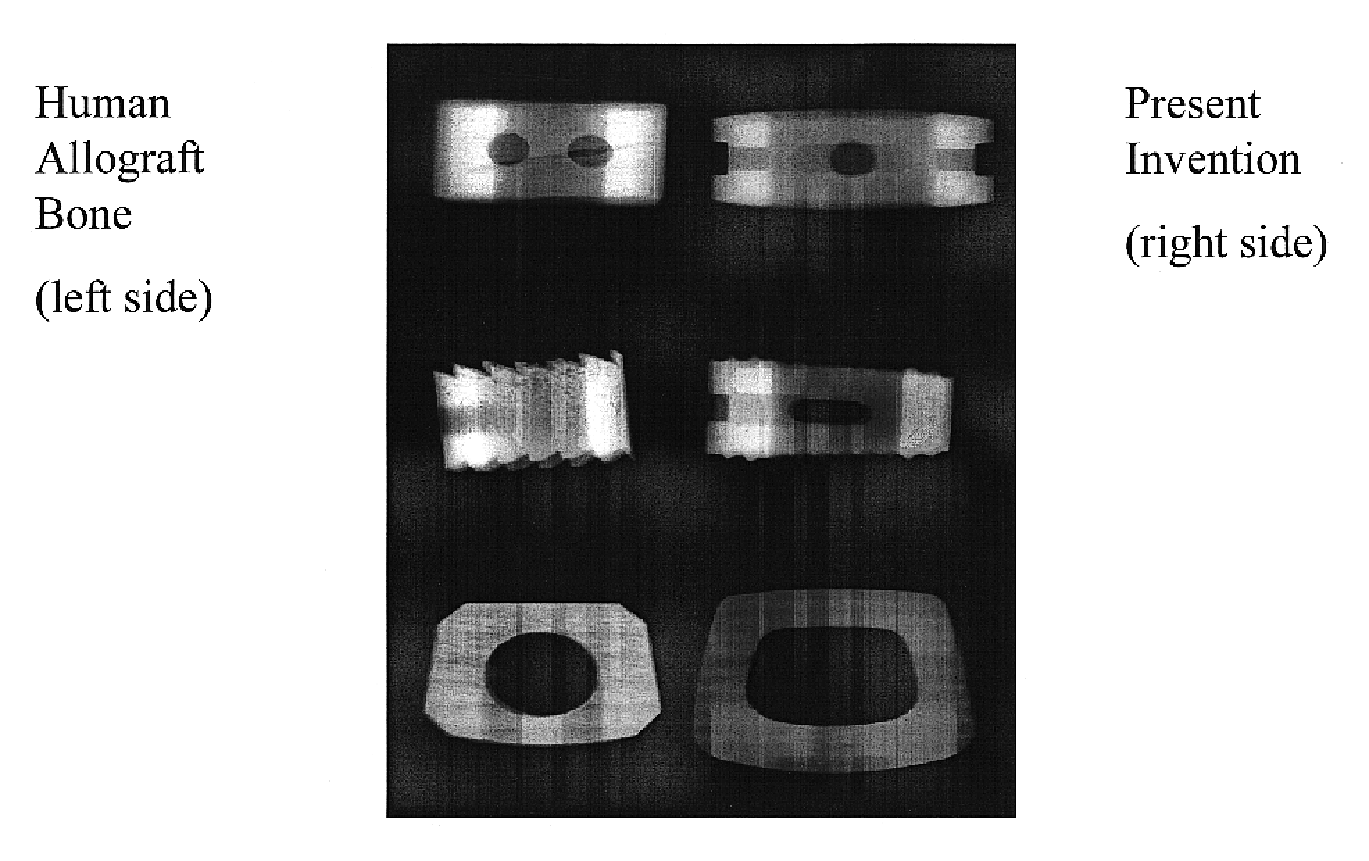
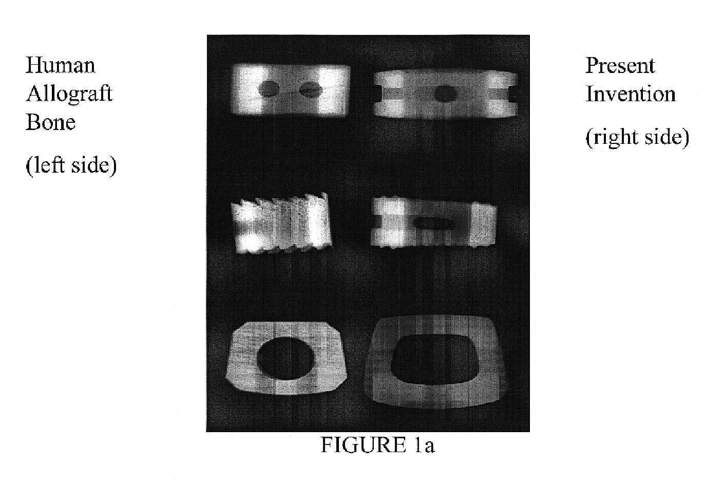
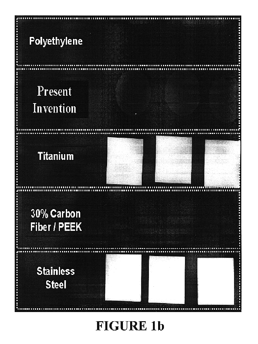
[0057]Qualitative Evaluation: Material of the present invention was prepared in the shape of an implant, which was placed along side an allograft implant for qualitative radiographic assessment as shown in FIG. 1a. Visually the samples had a similar radiographic appearance. In comparison to standard materials (FIG. 1b), the radiographic appearance of the material of the present invention most closely resembles bone. Variations of the present invention material can be formulated to produce variations in radiopacity as shown in FIG. 1c.

[0058]B) Quantitative Evaluation: Three tensile bar samples of polymerized bioactive material of the type described herein, approximately 4 mm in thickness, were arranged onto x-ray film, and a 16-step Aluminum step was placed on top. The 10-mm thick Aluminum step was placed so that it was partly shielding a polymerized sample and partly over x-ray film only (these materials were situated in a Faxitron ...

example 3

Mechanical Properties of a Bioactive Spinal Implant Material

[0074]Samples were prepared using the bioactive material described herein. Tests were performed using ASTM Guidelines on an Instron Model 8516 in order to obtain ranges of values of mechanical properties of the material as shown in the table below.

[0075]

TABLE IVMechanical Properties of a Bioactive Spinal Implant MaterialHUMAN CORTICALTESTRESULTBONE LITERATURECompressive Strength220-250MPa167-215MPaASTM F 451-95 & ASTMD695-91Compressive Modulus7.0-9.0GPa14.7-19.7MPaASTM F 451-95 & ASTMD695-91Compressive Yield Strength170-182MPa121-182MPaASTM F 451-95 & ASTMD695-91Tensile Strength65-100MPa70-140MPaASTM D638-98Tensile Elastic Modulus14-17GPa10.9-14.8MPaASTM D638-983-Point Flexural Strength100-120MPa103-238MPaASTM D790-90Shear by Punch Tool60-80MPa51.6MPaASTM D732-93Compressive Fatigue Strength170-190MPa>100MPa(106 cycles)Tensile Fatigue Strength35-55MPa49MPa(106 cycles)


PUM

PropertyMeasurementUnit
compressive strengthaaaaaaaaaa
temperatureaaaaaaaaaa

Abstract

Bioactive spinal implant materials having optimized radiopacity, stiffness, and bioactivity properties for formulation of shaped bodies capable of withstanding large dynamic, compressive loads are provided. The invention also provides methods of making the optimized implant materials.

Description

CROSS-REFERENCE TO RELATED APPLICATIONS[0001]This application claims priority to Provisional Application Ser. No. 60 / 339,871, filed Dec. 12, 2001, and Provisional Application Ser. No. 60 / 305,070, filed Jul. 13, 2001.FIELD OF THE INVENTION[0002]The present invention relates to spinal implant materials having optimized radiopacity, stiffness, and bioactivity properties and to methods of making such optimized spinal implant materials. The materials of the present invention can be used in a variety of orthopaedic applications, such as cervical fusion, anterior lumbar interbody fusion (ALIF) or posterior lumbar interbody fusion (PLIF). They may be implanted between adjacent vertebrae to treat or prevent back pain in patients with conditions such as degenerative disc disease.BACKGROUND OF THE INVENTION[0003]Lower back and neck pain is oftentimes attributed to the rupture or degeneration of intervertebral discs due to degenerative disk disease, spondylolisthesis, deformative disorders, tra...

Claims


Application Information

Patent Timeline
Patent Type & Authority Patents(United States)
IPC IPC(8): A61F2/28C08K3/40C08K3/34A61F2/00A61F2/02A61F2/30A61F2/36A61F2/44A61F2/46A61L27/44A61L27/50A61L31/16
CPCA61L27/446A61L27/50A61L31/18C08L33/06A61F2/44A61F2/36A61F2002/2892A61F2002/30062A61F2002/3008A61F2002/30957A61F2002/3631A61F2002/4649A61F2210/0004A61F2250/0098A61F2310/00017A61F2310/00023A61F2310/00293A61F2310/00329A61L2430/38A61F2/447A61F2/30965
Inventor ERBE, ERIK M.MURPHY, JAMES P.POMRINK, GREGORY J.
Owner ORTHOVITA INC
Why Eureka
Try Eureka