Check patentability & draft patents in minutes with Patsnap Eureka AI!

RF plasma method for production of single walled carbon nanotubes

Inactive Publication Date: 2006-05-30
ATS MER LLC
View PDF0 Cites 21 Cited by
  • Summary
  • Abstract
  • Description
  • Claims
  • Application Information

AI Technical Summary

Benefits of technology

[0032]An ICP reactor system was designed for SWNT production from solid carbon such as coal. This system offers the advantages of powder feedstock, continuous production and high throughput. The successful design utilizes a closed system as shown in FIG. 1. The high frequency power supply was a Lepel model T-40 (11) that powered a multi-turn water-cooled induction coil (12) wrapped around a water-cooled (13) reaction tube (14). A vibratory powder feeder (15) was used to shake coal / catalyst powder into the stream of argon that was maintained at a pressure of 300 torr. The powder entered the plasma (16), was vaporized and condensed into nanotubes and other products, which were collected in the trap (17). The pressure of the reactor is maintained using vacuum pump (18). The powder feeder is installed above the reactor (14) and its operation was flawless even though ultrafine powder was used. An alternative feeding mechanism is to fluidize the powder from the bottom into the hot plasma zone as shown in the schematic in FIG. 2. In this case the pressure control (28) and product collection (27) will be from the top. This approach allows for the control of the residence time of powder feed in the hot zone.
[0035]For plasma based reactor the mixture of the graphitized coal and / or graphite with the metal catalyst was used as is. This eliminates the rod fabrication step, which is expensive.
[0040]For production rate and scale up, it can be envisioned that this process is easy to scale up, being nearly continuous, and can be automated.
[0041]TEM is currently the most reliable method of analysis, since high resolution is required to discern individual nanotubes types, and to identify the bundle size and the SWNT dimension. Several analytical techniques are now available for determining the yield the SWNT. However it should be emphasized that the problem of evaluating the purity of SWNT sample is a difficult problem, and currently there is no protocol for comparison of SWNT yields in samples prepared by different techniques. This is especially true because of the inhomogenity in the samples. Two particular techniques are to some degree have been accepted by different groups working in this field. These two techniques are Raman spectroscopy and Thermogravimetric techniques. The thermogravimetric analysis (TGA) is used to decompose the sample in air, thereby selectively oxidizing the various particulate components of the soot sample. The nanotubes are more resistant to oxidation, and a weight percent measurement can be made. In addition, the amount of metal catalyst particles can also be readily analyzed from the weight of residue after the carbon materials are combusted. Raman spectroscopy gives a quantitative assessment of the types of SWNT in the sample. These analytical tools are complementary to the TEM analysis, and provide a less expensive and more rapid quantitative characterization of SWNT products. Both from TGA analysis and Aerial density measurement indicated that the yield of SWNT produced in the present system is comparable to the arc discharge method. However, the production rate is 12 times the rate of the arc process in only 20 mm diameter reactor. This result is very encouraging for further improvement and scale up.
[0042]We determined that initial problems with getting sufficiently hot plasma could be overcome by increasing the pressure of the argon atmosphere. In a preferred example, run conditions that were found to produce SWNTs were 400 torr Ar at a flow rate of 2.0 I / minute. Carbonized coal with 2–100 micron particle size was ball milled with 2.6 atomic % mixture of cobalt / nickel catalyst metals with Co:Ni ratio of 3:1 (atomic). This powder mixture was fed into the reactor (20-mm diameter) at a rate of 1.5 grams / minute. More optimization may improve nanotube yield, because the operating variables in this system are quite few and it is designed so that their optimization can potentially result in a practical and commercial method to produce large volume and low cost SWNTs. In addition, this technique takes real advantage of the low cost of powder carboneous materials like coal as the source of raw materials by using its natural powder form with simple pretreatment.

Problems solved by technology

It appears that during heating, the high-volatile coal becomes molten, and gasses that are evolved create a brittle, sponge-like cake.

Method used


Image

  • RF plasma method for production of single walled carbon nanotubes
  • RF plasma method for production of single walled carbon nanotubes
  • RF plasma method for production of single walled carbon nanotubes

Examples


example 1

[0057]SWNT are typically made from graphite rods that are drilled coaxially and tightly packed with a mixture of catalyst and graphite powder. Graphite rod with 5 / 16″ (8 mm) diameter was center drilled and packed with catalyst. The catalyst was 3:1 Co:Ni metal catalyst content was 11.5 wt %, which corresponds to 2.5 atomic % metal. The rods were vaporized by arcing the rods in an inert gas atmosphere using an arc reactor made of quartz chamber. From our extensive previous experience with graphite rod starting materials, the approximate conditions to produce SWNT from the catalyst-packed graphite were known. A gap is maintained by adjustment of the stepper motor speed. Pressure of helium, rod feed rate and current are maintained constant by instrument control. The voltage is allowed to vary, but remains relatively stable while equilibrium conditions of rod consumption are maintained. A single rod is consumed in about 60 minutes producing about 5 grams of products, and the products we...

example 2

[0061]Coal composite rods were made by mixing the treated coal / catalyst powder with pitch binder, then pressing 1×1×7.5 cm rods. The rods were then carbonized at 1000° C. in argon for two hours. The resultant rods had a density of approximately 1.7 g / cc, which is considered being very similar to commercial carbon rods. Cobalt: nickel catalyst with a 3:1 atomic ratio was used with 2.5 atomic % metal content in the finished rods. Coal composite rods were arced in the Quartz reactor described in example 1. The composite coal rod was installed in the lower electrode (anode), and is moved via a stepper motor to contact the broad upper electrode (cathode). A gap is maintained by adjustment of the stepper motor speed. Pressure of helium, rod feed rate and current are maintained constant by instrument control. The voltage is allowed to vary, but remains relatively stable while equilibrium conditions of rod consumption are maintained. A single rod is consumed in about 40 minutes producing ab...

example 3

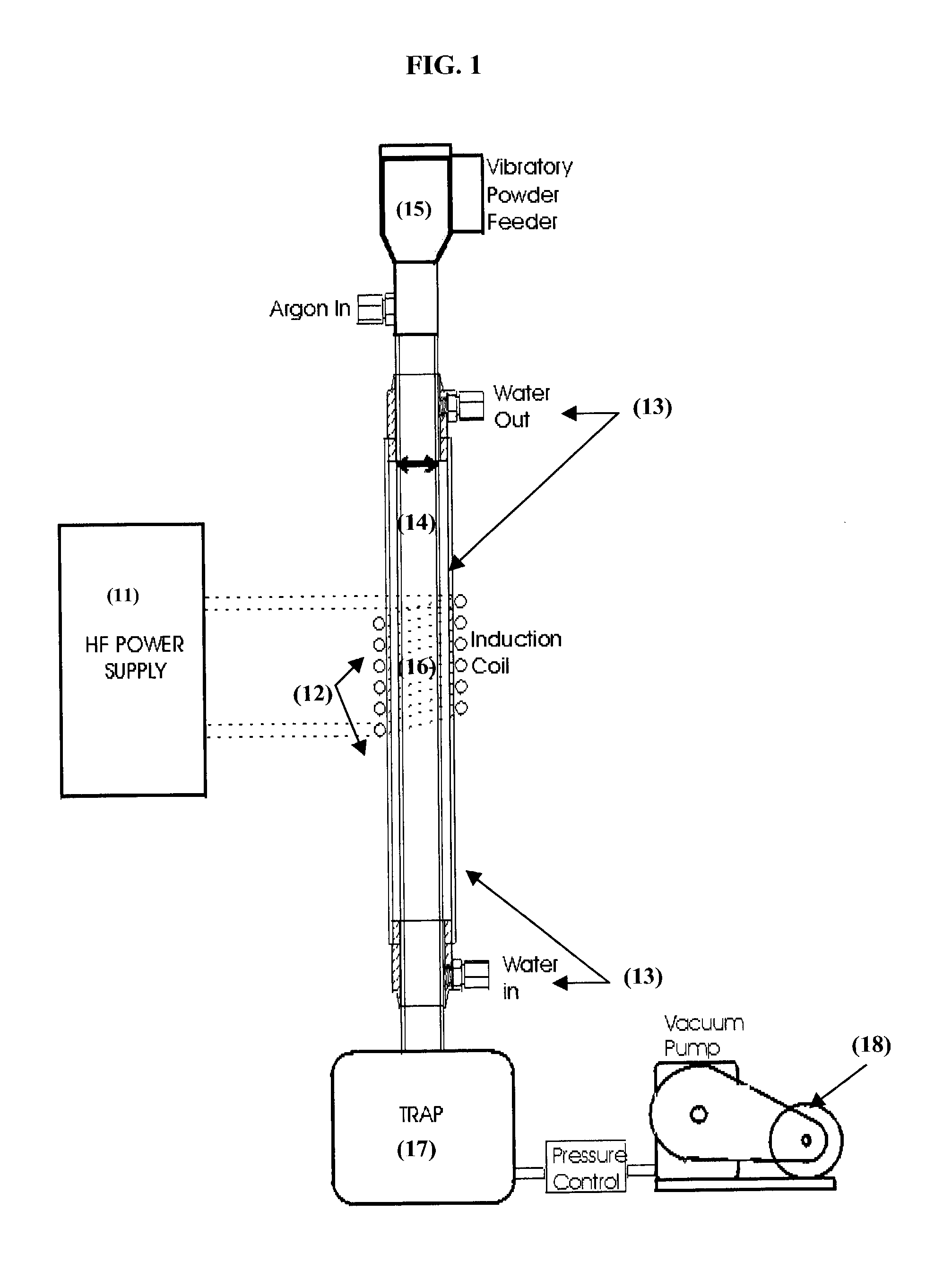
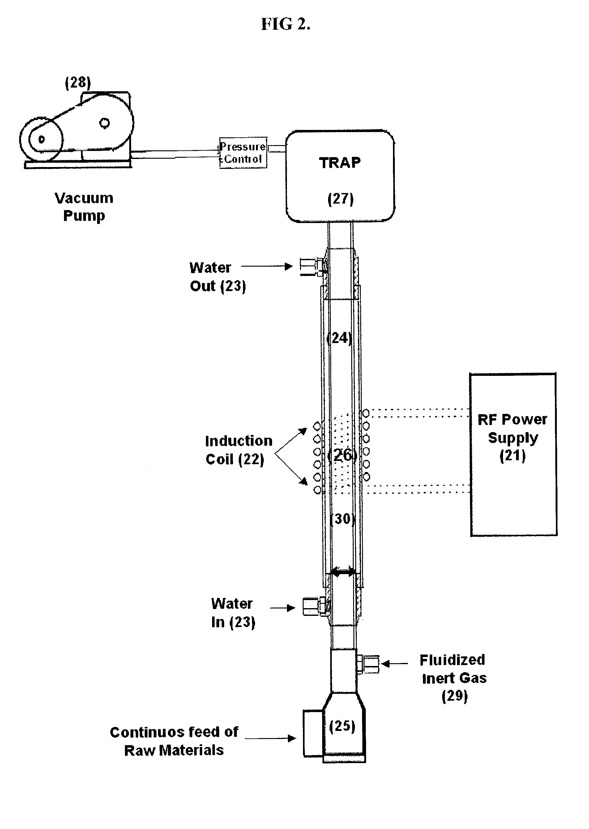
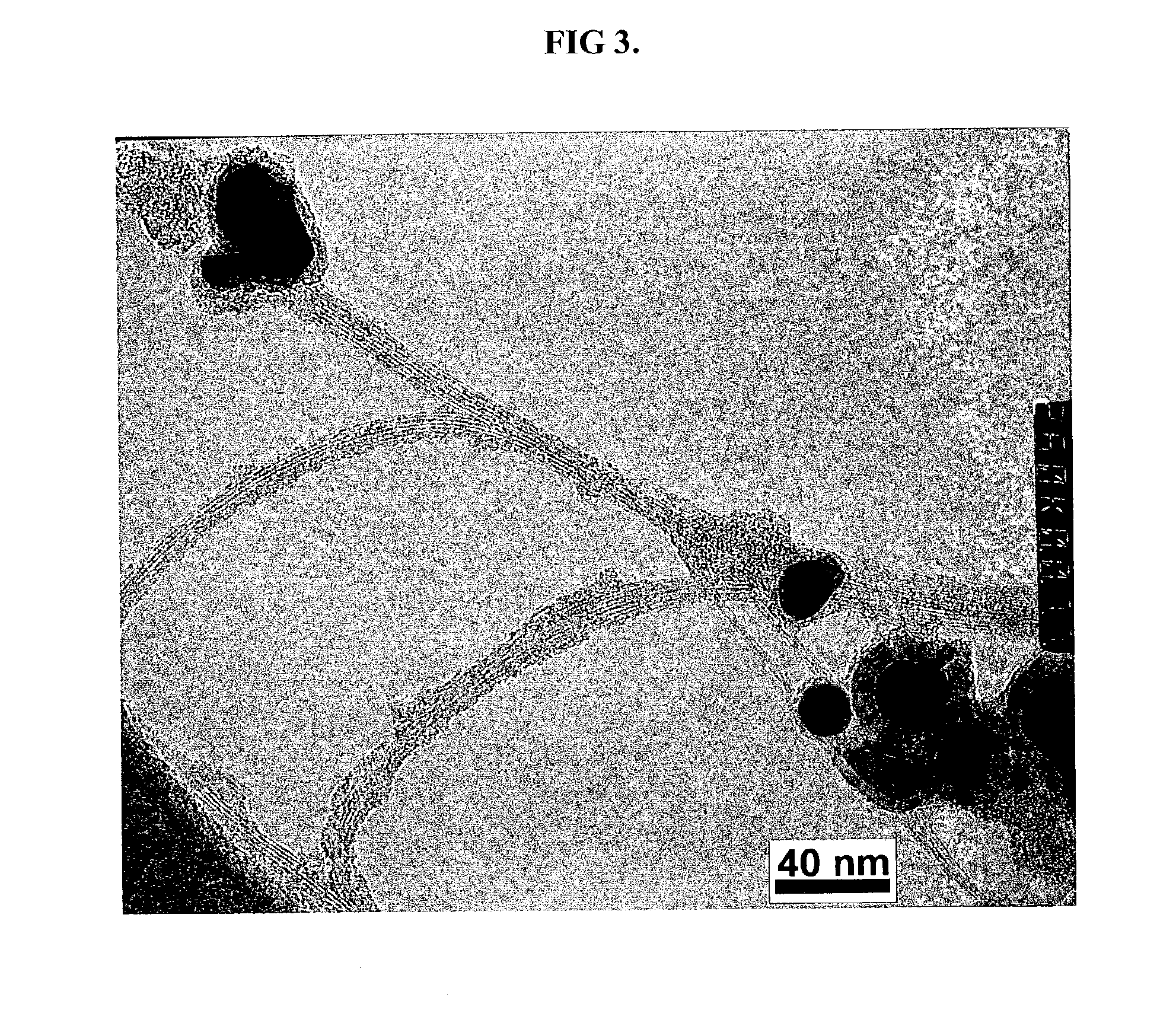
[0066]Carbonized coal with 2–100 micron particle size was ball milled with 2.6 atomic mixture of cobalt / nickel catalyst metals with Co:Ni ratio of 3:1 (atomic). This powder mixture was fed into the reactor system described in FIG. 1., at a variable rate from 1.5 grams / minute to 3 grams / minute. In a preferred example, run conditions that were found to produce SWNTs were 400 torr pressure, at an inert gas flow rate flow rate of 2.0 l / minute of argon. The induction coil used generated plasma at about 20 kw power. The standard LEPEL T-40 radio frequency generator was used. The reactor was a 20 mm inner diameter quartz tube, the created plasma ball was constrained within 10 cm3, which were the actual tube size and power levels employed in the experiments that demonstrated that the predicted yields could be obtained. The optimum feed rate where all feed was vaporized within the allowed residence time and plasma power conditions was found to be 1.5 gram / minute. A large number of TEM images...


PUM


Abstract

Single walled carbon nanotubes are selectively produced to the substantial exclusion of multi-walled carbon nanotubes by subjecting a mixture of solid hydrocarbon, such as coal, and a transition metal catalyst, to heat generated by an RF induction system sufficient to vaporize both the solid hydrocarbon and the catalyst, and thereafter collecting the single walled carbon nanotubes thereby formed.

Description

[0001]This application claims the benefit of U.S. Provisional Application No. 60 / 339,078, filed Oct. 30, 2001.FIELD OF INVENTION[0002]The present invention relates to methods and apparatus for producing carbon nanotubes, by vaporizing carbonaceous material, and metallic catalytic materials in a high temperature environment produced by a plasma, and, more particularly, to the production of single walled nanotubes “SWNTs” using a radio frequency generated plasma as the heat source to vaporize the carbonaceous and catalytic materials.BACKGROUND OF THE INVENTION[0003]Because of their unique structure, physical and chemical properties the recently discovered fullerene nano-tube (Single-Walled Nano-Tubes; SWNT) materials have been investigated for many applications. Indeed this is one material from which the application development has out-paced its mass availability. The most added-value applications that are being developed using nanotubes include Field Emission Devices, Memory devices ...

Claims


Application Information

Patent Timeline
IPC IPC(8): D01F9/12D01F9/127
CPCB82Y15/00D01F9/127B82Y30/00
Inventor LOUTFY, RAOUF O.MORAVSKY, ALEXANDER P.LOWE, TIMOTHY P.
Owner ATS MER LLC
Features
  • R&D
  • Intellectual Property
  • Life Sciences
  • Materials
  • Tech Scout
  • Unparalleled Data Quality
  • Higher Quality Content
  • 60% Fewer Hallucinations
Learn More