
Micro-array evanescent wave fluorescence detection device

a fluorescence detection and microarray technology, applied in the field of detection of molecules, can solve the problems of affecting cell or protein function, manual and time-consuming, sample preparation currently represents a major component of time, labor and cost in sequencing, and achieve the effect of detecting advantageously

Inactive Publication Date: 2007-02-13
EDGELIGHT BIOSCI
View PDF26 Cites 141 Cited by
  • Summary
  • Abstract
  • Description
  • Claims
  • Application Information

AI Technical Summary

Benefits of technology

[0058]The present invention addresses the above-identified need by providing a system and method for enhanced evanescent wave detection of bound biological molecules, individual spot configuration control and ease in manufacturing for use in diagnostic and related applications.

Problems solved by technology

Any defect or mutation in the sequence of nucleotide bases in the DNA or RNA can disrupt cell or protein function and lead to disease.
Preparation of a DNA sample for analysis includes manual and time-consuming laboratory processes such as centrifugation, filtration, measuring, mixing and dispensing.
It is believed that sample preparation currently represents a major component of the time, labor and cost in sequencing.
In addition, the manual nature of these steps renders sample preparation prone to human error, which can compromise the quality of information obtained from the sample.
While the throughput has increased with successive generations of gel-based sequencers, a significant amount of labor is still required to operate a gel-based sequencer.
The labor involved in gel-based sequencers includes the time consuming tasks of preparing a new gel for each separation, loading each DNA sample onto the gel and cleaning the system after each separation.
Sequencing all of the DNA in a complex genome is a massive undertaking and, despite recent increases in throughput, requires up to hundreds of sequencers running in parallel for months or even years.
In addition, the initial sequence of a genome typically contains errors, which then require additional sequencing to correct.
Existing genotyping technologies do not provide the throughput, automation or economy needed for high throughput SNP analysis.
Researchers can only analyze one DNA sample on each microarray.
Thus, microarrays offer a high degree of multiplexing but provide low sample throughput.
Thus, the overall throughput of enzyme methods is also relatively low.
Researchers can use hybridization microarrays to monitor thousands of genes at the same time, but this approach is only feasible for relatively small numbers of samples, because only one DNA sample can be analyzed per individual microarray.
Current assay development methods are time consuming, taking from weeks to months, and are labor intensive, largely due to the need to measure a particular molecule within a mixture of many different components.
In addition, current technologies for performing assays provide only a fraction of the information needed for selecting potential drug candidates.
For example, existing technologies only allow researchers to measure a single gene at one time for the purposes of monitoring gene expression.
Existing detection methods also typically require preparation of reagents in a highly purified form, which requires additional time and labor.
The time, expense and labor required to conduct a primary screen currently limits the number of screens that pharmaceutical researchers perform, and thereby limits their opportunities for discovering new drugs.
A major element of cost in primary screening comes from the amount of chemical and biochemical reagents, including the drug target, required to perform large numbers of assays.
Because of the high cost and the limited availability of many reagents, researchers have attempted to reduce the total consumption of reagents by reducing the volume of each measurement from hundreds of microliters down to three to five microliters.
The success of these efforts, however, has been limited by the effects of evaporation on small sample volumes, the sensitivity of existing detection methods and the difficulty of delivering small volumes of reagents to microwell plates with speed and precision.
For example, a volume of one microliter can evaporate from an open well in a few minutes, and even a small amount of evaporation reduces the reliability and precision of a measurement.
This conflicts, however, with the objective of reducing reagent consumption.
Current technologies typically measure only a single data point at a time, such as the activity of one compound on a particular enzyme, limiting the efficiency and economy of secondary screening, as well as the efficiency of overall pharmaceutical research.
If it is expressed in another way, it may result in a turmor.
The major problem with single mode systems is that the fiber or planar waveguides are very small in size as compared to a multimode waveguide system, making source and detector coupling very difficult.
The launching of light and overall manufacturing of system using single mode structures is difficult and expensive.
However, the Modlin device and approach has some serious disadvantages including the need for highly specialized plates and machinery where alignment is critical.
It is also requires comparatively large volumes if sample and analyses and is not providing the commercially practical solution which are still sought.
Confocal microscopy detection is often used to interrogate fluorescent signals matrixed on micro-arrays however such devices are disadvantageously expensive thereby limiting their commercial practicality in the clinical laboratory setting.
If the spots are too close together on a highly wettable surface, cross-contamination occurs.
Each micro-array system representing the current state of the art fails to adequately address the growing need for low-level detection, the control of individual micro-array spotted chemistries in a close packed density and a cost effective, manufacturable system.

Method used


Image

  • Micro-array evanescent wave fluorescence detection device
  • Micro-array evanescent wave fluorescence detection device
  • Micro-array evanescent wave fluorescence detection device

Examples


example

[0111]Prototype chemical sensor waveguide devices were created by bonding a glass fiber optic wire to a flat polymer waveguide. The flat polymer material used for the waveguide is described in Table 1 of U.S. Pat. No. 5,402,514 fully incorporated herein by reference. A fiber optic wire was disposed in such a way that emitted light would be coupled or launched into the waveguide and travel through the waveguide generally parallel to the surface of the waveguide. The other end of the fiber optic wire was attached to a helium-neon laser light source. Therefore, the light was transmitted through the fiber optic wire and entered the polymer waveguide. Red light from the helium-Ne laser was visible inside the waveguide. A cladding layer of cellulose acetate butyrate (“CAB”) with a refractive index lower than that of the polymer waveguide material was bound to liquid polyguide material at one side of the waveguide. A cladding layer of CAB was bound to the other side of the flat polymer wav...


PUM

PropertyMeasurementUnit
timeaaaaaaaaaa
volumeaaaaaaaaaa
volumeaaaaaaaaaa

Abstract

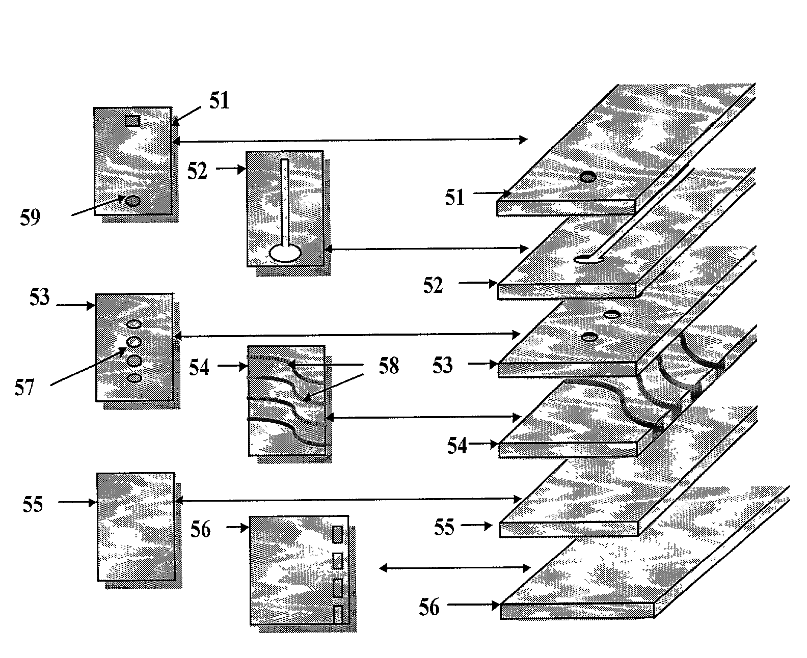
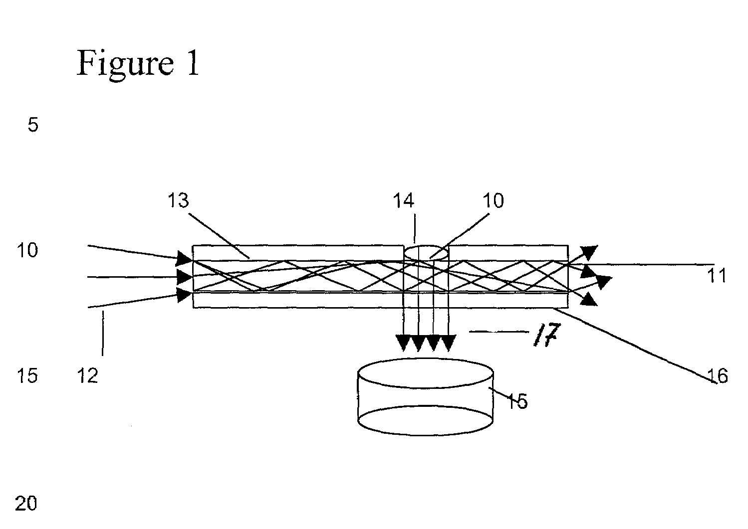
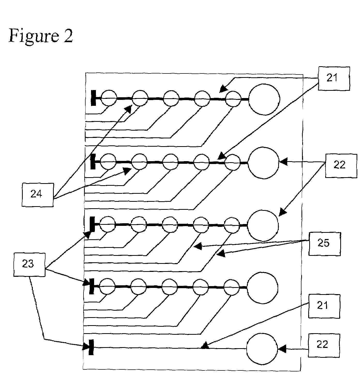
Novel nanowell microarrays are disclosed in optical contact with polymer waveguides wherein evanescent field associated with lightwaves propagated in the waveguide excite target substances in the nanowells either by a common waveguide or by individual waveguides. Fluid samples are conveyed to the nanowells by means of microfluidics. The presence of the target substances in fluid samples is detected by sensing fluorescent radiation generated by fluorescent tag bound to the target substances. The fluorescent tags generate fluorescent radiation as a result of their excitation by the evanescent field. One or more PMT detectors or a CCD detector are located at the side of the waveguide opposite to the nanowells. Fluorescent radiation is detected due to its coupling with the waveguide or its emission through the waveguide.

Description

RELATED APPLICATIONS[0001]This application claims the priority filing benefit of U.S. provisional patent application 60 / 200,574, filed on Apr. 28, 2000, which is incorporated herein by reference.FIELD OF THE INVENTION[0002]The present invention relates generally to the detection of molecules, such as biological molecules. More specifically, the invention relates to the system and method of detecting biological molecules bound to an array of micro wells provided in and optically associated with a waveguide. The evanescent wave created by the electromagnetic radiation propagating in the waveguide interacts with the fluorescent or other tags bound to the molecules, generating emitted fluorescent or other signal and allowing the detection of the biological molecules.BACKGROUND OF THE INVENTION[0003]Life science research has been undergoing a transition in recent years to large-scale experimentation, where a single project can require hundreds or thousands of measurements. Two fields tha...

Claims


Application Information

Patent Timeline
Patent Type & Authority Patents(United States)
IPC IPC(8): G01N21/01B81B1/00C12Q1/68C12Q1/6825G01N21/55G01N21/64G01N21/77G01N33/543G01N33/566G01N37/00G02B6/122G02B6/138
CPCB82Y5/00B82Y15/00C12Q1/6825G02B6/138G01N21/6452G01N21/648G01N21/6428B01J2219/00274G01N2021/7786
Inventor BACH, DAVIDBOOTH, BRUCE L.RICHARDS, JAMES C.
Owner EDGELIGHT BIOSCI
Learn More