
Metal stent with surface layer of noble metal oxide and method of fabrication

a metal oxide and metal stent technology, applied in the field of body implantable stents, can solve the problems of drug-coated stents, angina or even myocardial infarction, hyperplasia and resulting restenosis,

Inactive Publication Date: 2008-07-22
BOSTON SCI SCIMED INC
View PDF156 Cites 58 Cited by
  • Summary
  • Abstract
  • Description
  • Claims
  • Application Information

AI Technical Summary

Benefits of technology

The solution provides a stent with improved mechanical strength, radiopacity, biocompatibility, and reduced restenosis risk, maintaining vessel patency and visibility under fluoroscopy, while ensuring long-term stability and minimizing allergic reactions.

Problems solved by technology

The artery blockage may be detected through an electrocardiogram performed during the individual's visit to a doctor, or be so extreme as to result in angina or even myocardial infarction.
The presence of the stent in contact with the vessel wall, however, can promote hyperplasia and resulting restenosis, and, along the stent's inner surface, may promote thrombus formation with the perfusion of blood through the stent's lumen.
Drug coated stents are considerably more expensive than uncoated stents, and may be unnecessary for a relatively large percentage of angioplasty patients in which they are implanted, being prescribed solely to avoid the possibility of an undesirable reaction soon thereafter.
On the other hand, the use of uncoated stents has its own set of problems even beyond possibly inducing a traumatic response along the vessel wall or promoting thrombosis along the stent's lumen.
Wholly biodegradable stents of possibly sufficient radial strength are undergoing testing but appear unlikely to constitute a breakthrough or a satisfactory solution in these cases.
A 70 to 80 μm thick 316L steel stent, for example, offers sufficient mechanical strength for the aforementioned purposes, but is too thin to create the shadow needed for fluoroscopic viewing because the x-ray absorption of this metal is so low.
Increasing the wall thickness of the stent to enhance its radiopacity makes the stent less flexible, which adversely affects its maneuverability through narrow vessels during implantation, and its ease of expansion during deployment, with concomitant increased risk of balloon rupture.
Despite improvements in the design, construction and coating of coronary stents, restenosis remains a problem.
A major contributing factor is the inability of the body to quickly incorporate the implanted foreign material of the stent.
It had been assumed by industry practitioners and researchers that a highly polished and smooth surface is beneficial to prevent stent thrombosis and to facilitate endothelialization, but more recent experiments indicate this may not be entirely true.
The presence of cracks or related defects in the surface coating can produce a galvanic potential that could ultimately lead to corrosion of the underlying steel or lesser metal, an unacceptable situation for a device intended to be permanently implanted in the body.
Therefore, manufacturing requires a high degree of quality control and concomitant high cost.
But it is expensive to produce.
A stability problem may be encountered in the bond between the noble metal oxide layer, such as iridium oxide, and a non-noble or less-noble metal, alloy or compound, such as niobium or platinum enriched medical grade stainless steel.
During the bonding process the less noble metal tends to draw or leach oxygen atoms from the noble metal, which causes depletion of oxygen from the latter metal.
The result can be a less stable, less satisfactory bond or adhesion between the two layers.
In addition, in the case of an iridium oxide layer as the noble metal oxide, the oxygen depletion leaves that layer less effective as a stenosis or restenosis inhibitor.

Method used


Image

  • Metal stent with surface layer of noble metal oxide and method of fabrication
  • Metal stent with surface layer of noble metal oxide and method of fabrication
  • Metal stent with surface layer of noble metal oxide and method of fabrication

Examples


Embodiment Construction

[0030]It is to be understood that none of the drawing figures is intended to be a representation to scale of the respective depicted embodiment.

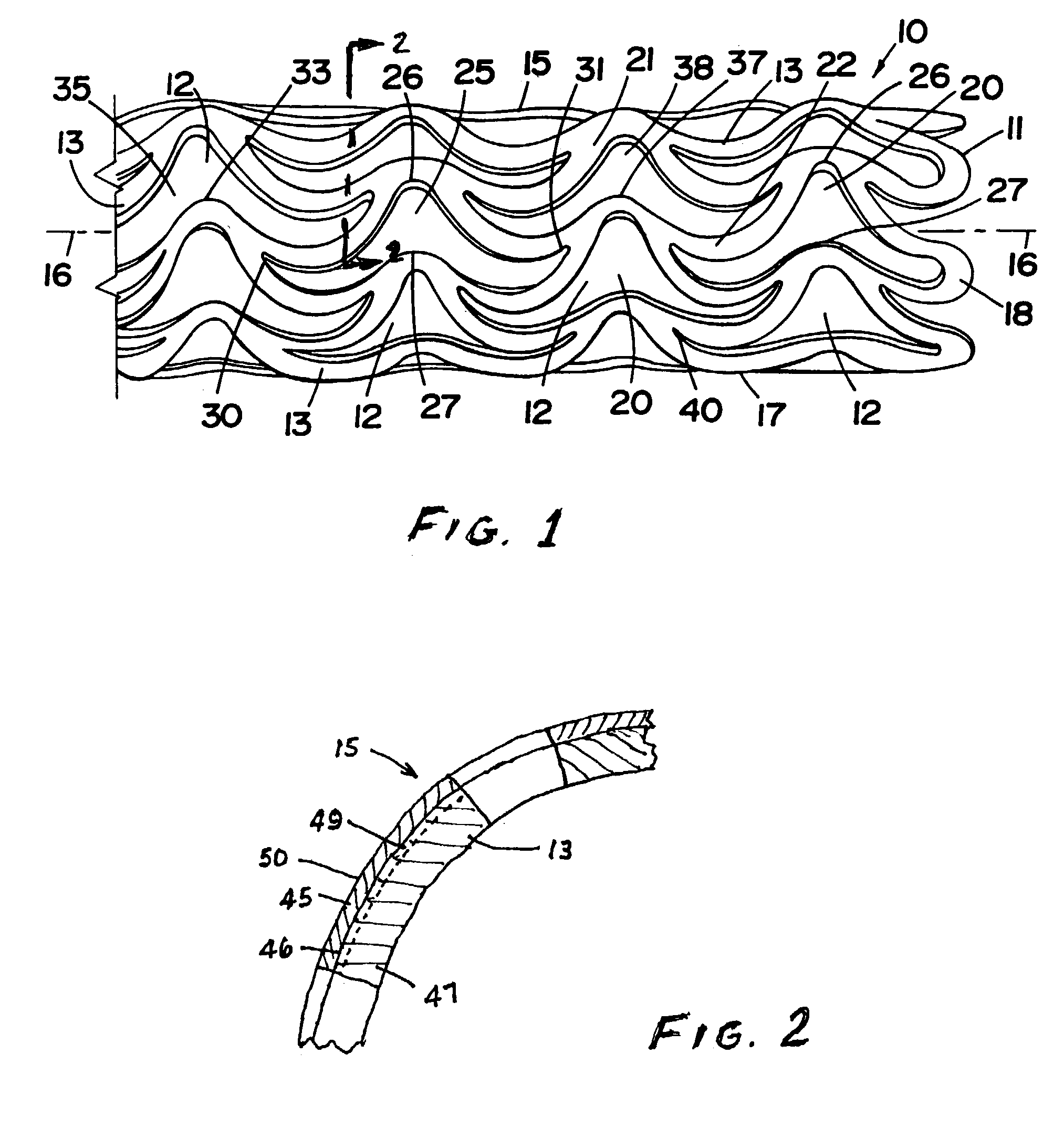
[0031]FIG. 1 is a perspective view of a stent 10 of hollow tubular self-supporting structure, with a substrate or core composed preferably of niobium (Nb) with a trace of zirconium (Zr), titanium (Ti) or tantalum (Ta), for example, preferably zirconium, the trace amount preferably being between approximately 1% and approximately 5%, and most preferably being about 2%, and remainder niobium. The added trace metal improves physical characteristics including strength of the stent for its intended function. Typically, the niobium stent material includes negligible amounts of tantalum (Ta, about 180 micrograms per gram (μg / g)), iron (Fe, <20 μg / g), silicon (Si, about<20 μg / g), tungsten (W, <20 μg / g), molybdenum (Mo, <20 μg / g), hafnium (Hf, <20 μg / g), carbon (C, about 7 μg / g), and nitrogen (N, about 53 μg / g), as well as amounts of hydrogen (H) and...


PUM

PropertyMeasurementUnit
thicknessaaaaaaaaaa
thicknessaaaaaaaaaa
thicknessaaaaaaaaaa

Abstract

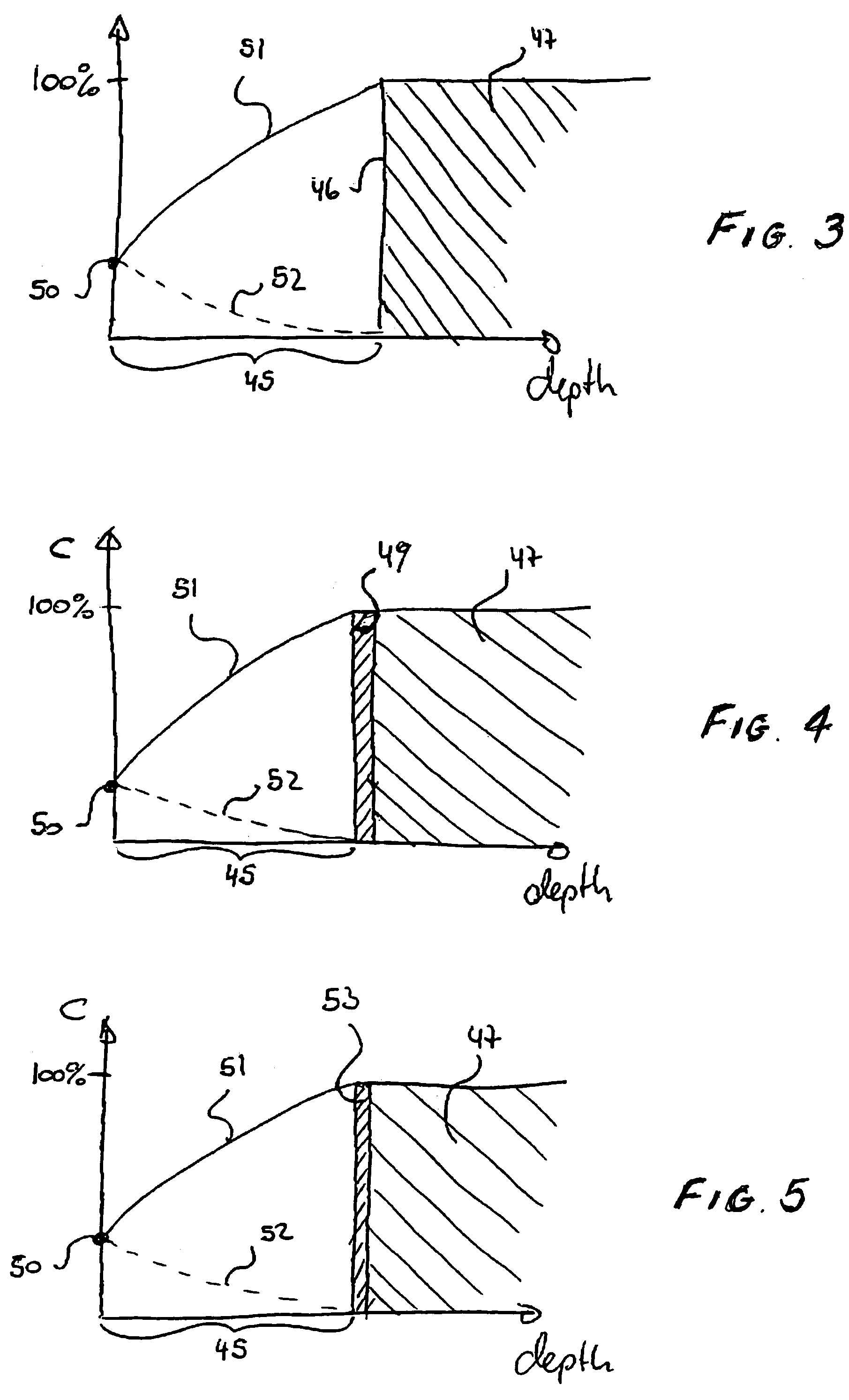
In a process for producing a biocompatible stent, a tubular substrate of the stent adapted for diametric expansion has a layer of a noble metal oxide formed over at least the outer surface of greater diameter of the substrate, the substrate being composed of a metal or an alloy thereof that is non-noble or less-noble than the layer's noble metal. An interface region adapted to prevent corrosion and to provide a firm bond between the surface of the substrate and the noble metal oxide layer is established, at least in part, by forming the noble metal oxide layer with a progressively varying concentration of noble metal-to-oxide with depth of the layer such that a surface of pure noble metal and negligible oxide of the layer is in closest proximity to the surface of the substrate. In one embodiment of the process, the interface region is established by forming the surface of pure noble metal and negligible oxide thereof in direct contact with the metal or alloy of the substrate surface. In another, the interface region is established by first creating an oxide of the substrate metal or alloy thereof at the substrate surface, and then forming the noble metal oxide layer as above, but in contact with the substrate metal or alloy oxide. Alternatively, the noble metal oxide layer has no progressively varying concentration but simply overlies an oxide of the substrate metal or alloy.

Description

BACKGROUND OF THE INVENTION[0001]The present invention relates generally to body implantable stents, deployed in a vessel, tract, channel or duct, such as a coronary artery or femoral artery of a patient to maintain its lumen open for satisfactory blood flow therethrough, and more particularly to methods of producing multi-layer stent structures in which an oxide of a noble metal or alloy is bonded in a firm and stable relationship to an underlying non-noble or less-noble metal, and to such stent structures themselves.[0002]When inserted and deployed in a vessel, duct, channel or tract (referred to generally herein, for convenience, as a vessel) of the body—for example, a coronary artery after dilatation of the artery by balloon angioplasty—a stent acts as a scaffold to maintain the vessel's lumen open. The stent prosthesis is structured as an open-ended tubular element with through-holes in its sidewall to allow expansion of its diameter from a first sufficiently small size to perm...

Claims


Application Information

Patent Timeline
Patent Type & Authority Patents(United States)
IPC IPC(8): A61F2/06A61M29/00A61F2/00A61F2/90A61L31/02A61L31/08A61L31/18
CPCA61F2/91A61F2/915A61L31/18A61L31/022A61L31/088A61F2002/91541A61F2310/00598A61F2002/91558
Inventor SCHEUERMANN, TORSTENSTEHLING, LUTZ
Owner BOSTON SCI SCIMED INC
Learn More