
Method and system for transmitting terahertz pulses

a terahertz pulse and beam technology, applied in waveguides, optical radiation measurement, instruments, etc., can solve the problems of limited progress, sample or region to be studied may not be readily accessible to a line-of-sight beam, and rely on free-space transport of terahertz beams. , to achieve the effect of low loss

Inactive Publication Date: 2009-05-12
RICE UNIV
View PDF13 Cites 263 Cited by
  • Summary
  • Abstract
  • Description
  • Claims
  • Application Information

AI Technical Summary

Benefits of technology

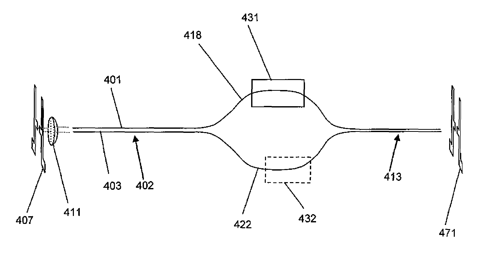
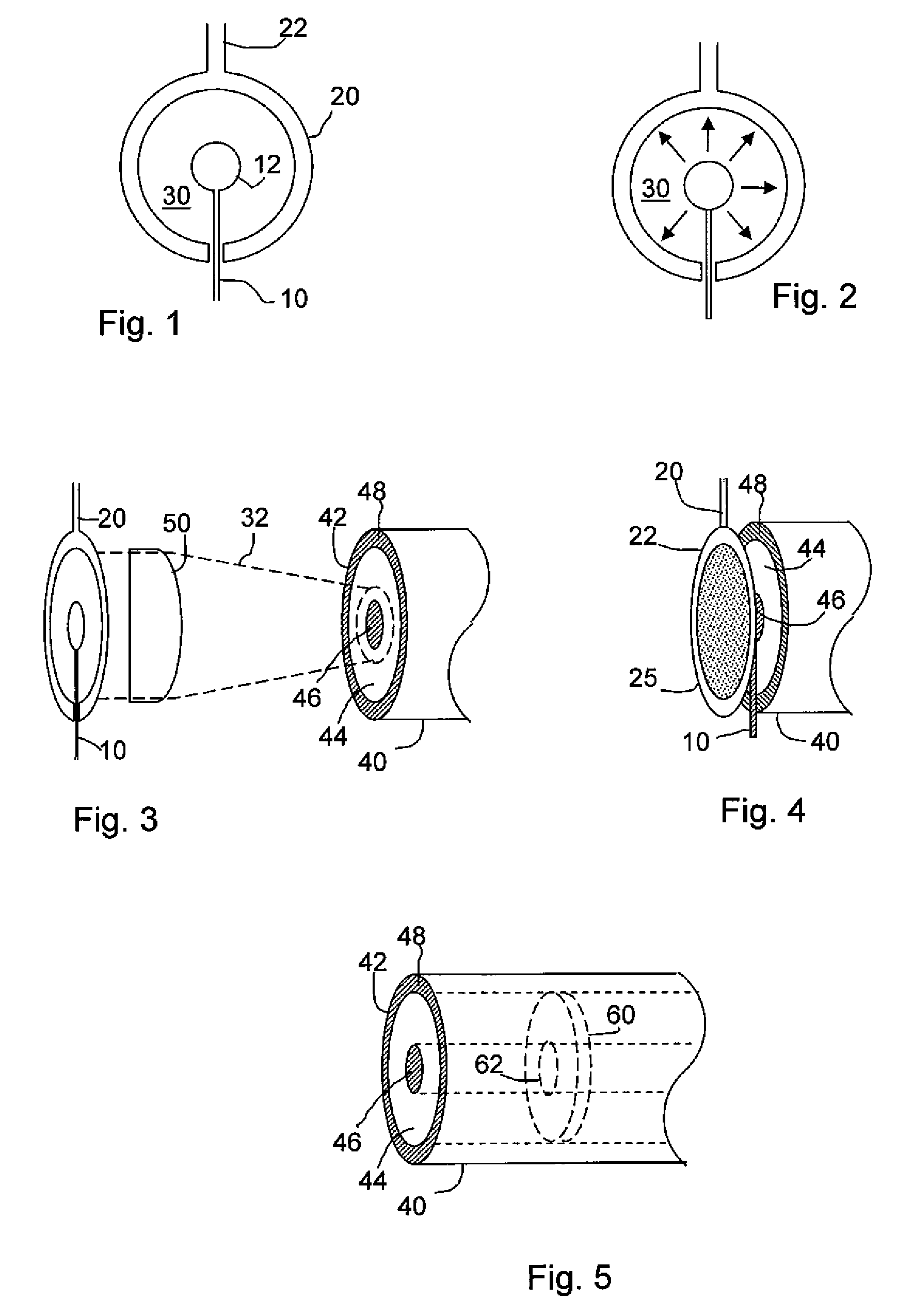
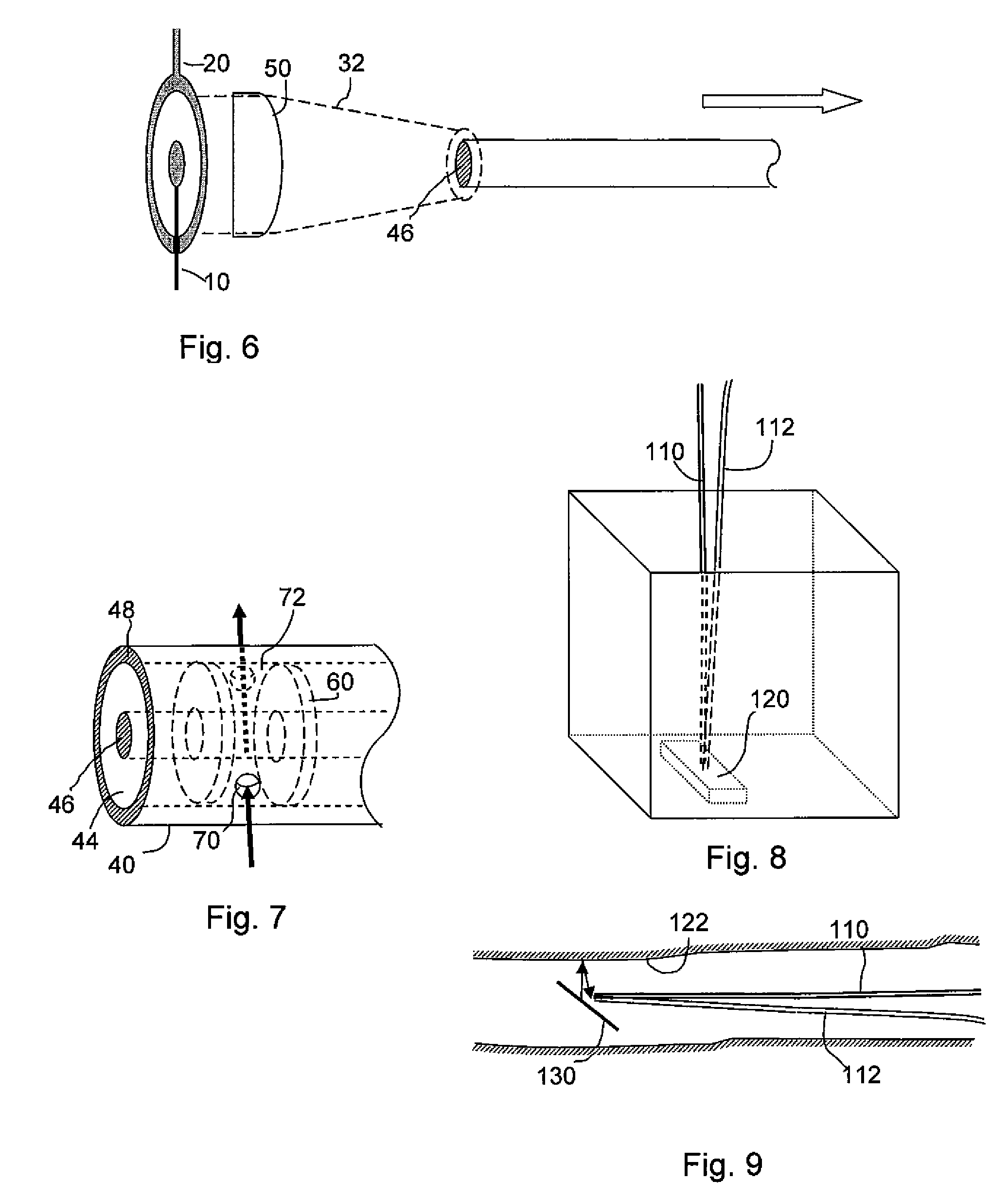
The patent describes new types of waveguides for transmitting THz signals with low loss and negligible group velocity dispersion. These waveguides enable many new sensing applications, such as directing THz pulses inside containers or around corners where line-of-sight optics are not practical. The systems also allow the use of either radially polarized or linearly polarized THz antennas. The patent also describes a terahertz transmitting system that includes an antenna and a waveguide with two or more conductive elements, and a method for transmitting a THz signal using a coaxial antenna and a coaxial or uniaxial waveguide. The patent also describes a terahertz interferometer that includes a primary waveguide with at least two conductive elements that rejoin to form a secondary waveguide and a detector. The invention provides a simple and effective solution for guiding THz pulses with low loss and negligible group velocity dispersion.

Problems solved by technology

However, progress is limited by the overwhelming reliance on free-space transport of the terahertz beam, using bulk optical components.
In many real-world situations, the sample or region to be studied may not be readily accessible to a line-of-sight beam.
In addition, while THz waves can be transmitted simply by free space propagation, free space propagation requires bulk optical components, which are difficult to align.
Heretofore, the development of THz waveguides has been hindered by the material properties and the application requirements in this spectral range.
On the one hand, the characteristics of materials at THz frequencies make it extremely difficult to build a fiber to guide THz beams over a long distance.
The most transparent materials for this range are crystalline (e.g., high resistivity silicon), and thus are costly, fragile, and challenging to form into specific geometries for waveguide configurations.
Other materials, such as low-loss polymers or glasses, are more malleable but exhibit prohibitively high absorption losses for propagation distances of more than a few centimeters.
But for many conventional metal waveguides (e.g., metal tubes), pulse reshaping in propagation is difficult to avoid, due to the extreme dispersion near the waveguide cutoff frequencies.
Furthermore, finite conductivity of metals can lead to considerable losses in the wave propagation.
In all of these cases, the utility for transport of THz pulses is limited by group velocity dispersion of the guided waves.
In the parallel plate design, the loss is attributable to two factors: (1) lateral spreading due to the fact that the mode is unconfined in one of the two transverse dimensions, and (2) the finite conductivity of the metal used to confine the mode, which in this case results in a reported attenuation of ˜80 dB / m.
Furthermore, the attenuation is still unacceptably high, due in large part to the finite conductivity of the metal plates.
In addition, the cross-sectional area of the waveguide is too large for many of the proposed THz applications, including in particular medical diagnostics.

Method used


Image

  • Method and system for transmitting terahertz pulses
  • Method and system for transmitting terahertz pulses
  • Method and system for transmitting terahertz pulses

Examples


example 1

Propagation Effects in Near-Field Optical Antennas

[0078]The propagation of THz radiation along bare metal wires was first observed in the demonstration of apertureless near-field scanning optical microscopy (NSOM) using THz-TDS. The experimental setup is depicted in FIG. 12. The broadband single-cycle pulses of free-space THz radiation were generated using a photoconductive transmitter and were focused onto a beryllium-copper probe acting as an apertureless near-field optical antenna. The probe had a tip of about 25 μm radius and a shaft of 0.5 mm diameter coated with a thin layer of tin to prevent oxidation. The sample was a featureless gold-coated silicon wafer, placed in close vicinity of the tip. The mean distance between the tip and the gold surface, d˜350 nm, was precisely controlled by a piezoelectric transducer. In such a configuration, the tip strongly interacted with its image in the metal surface, and converted the localized evanescent field around the tip to propagating ...

example 2

Direct Characterization of a THz Wire Waveguide

[0081]For a better observation and characterization of the guided THz propagation on metal wires, we changed the experimental setup from the NSOM configuration to a new configuration in which the electric field of the guided mode was directly detected at the end of the waveguide. With the fiber-coupled transmitter and receiver, the incident position (the start point of the propagation) and the detection position of the THz pulses were changed to observe the spatial profile of the guided mode. A long stainless steel wire with a smooth surface, rather than the tiny tapered probe in the NSOM experiments, was used as the waveguide for the new measurements.

Experimental Setup

[0082]A schematic illustration of the new experimental setup is shown in FIG. 13. As in the NSOM experiments, the broadband single-cycle pulses of free-space THz radiation were generated and coherently detected using ultrafast photoconductive sampling. The horizontally po...

example 3

Manipulation of the Guided Pulses

[0096]The manipulation of the guided mode was next studied. The ability to direct radiation along curves is one of the most important features for a practical waveguide. The amplitude of THz pulses was compared after propagating on a waveguide bent with different radii. The results are shown by the hollow triangles in FIG. 18. The propagation distance was 21 cm, and the radius of curvature R was varied from 90 cm down to 20 cm in steps of 10 cm. The amplitude of the electric field E′ as a function of the propagation distance x along the bent waveguide is described by

E′(x)=E0e−α′x  (6)

where α′ is the amplitude attenuation coefficient for a bent waveguide. By comparing equation (6) to equation (5) we find

[0097]α′=α+ln⁡(EE′)x(7)

So the amplitude attenuation coefficient for each bend radius was extracted by comparing the amplitude of the detected THz pulse to that of a straight waveguide with the same propagation distance x. The extracted data are depicte...


PUM

PropertyMeasurementUnit
wavelengthsaaaaaaaaaa
bend radiiaaaaaaaaaa

Abstract

Systems for THz transmission using new types of THz waveguides with low loss, negligible group velocity dispersion and structural simplicity are described herein. The THz system incorporates the use of a waveguide with two or more substantially parallel conductive elements which may enable many new THz sensing applications. It is now possible to direct the THz pulse inside of containers or around corners, where line-of-sight optics are not practical. Moreover, the systems allow use of either radially polarized or linearly polarized THz antennas. The disclosed systems are compatible with existing terahertz generation and detection techniques.

Description

CROSS-REFERENCE TO RELATED APPLICATIONS[0001]The present application claims the benefit of U.S. Provisional Application Ser. No. 60 / 807,380 filed Jul. 14, 2006, herein incorporated by reference in its entirety for all purposes.TECHNICAL FIELD OF THE INVENTION[0002]This invention provides a method and system for guiding terahertz pulses over practical distances with low loss and low dispersion.BACKGROUND OF THE INVENTION[0003]Rapid advances in laser technology have enabled various techniques for the generation and detection of electromagnetic radiation in the terahertz region (spanning from ˜100 GHz to ˜10 THz, or wavelengths between ˜30 μm and ˜3 mm). As a result, numerous uses of terahertz radiation have been explored, including trace gas detection, medical diagnosis, security screening, and defect analysis in complex materials such as space shuttle tiles. Many of these studies have relied on terahertz time-domain spectroscopy, a technique for generating sub-picosecond pulses with ...

Claims


Application Information

Patent Timeline
Patent Type & Authority Patents(United States)
IPC IPC(8): G01N21/35H01P3/02
CPCG01J3/42G01N21/3581G01N21/3504G01N21/3563
Inventor MITTLEMAN, DANIEL M.DEIBEL, JASON A.ESCARRA, MATTHEW
Owner RICE UNIV
Learn More