
Dry process rotary kiln cement production line based facility and method for cooperatively processing electrolytic manganese residues

A technology of electrolytic manganese slag and synergistic treatment, applied in cement production, lighting and heating equipment, preheating costs, etc., can solve the problems of unsatisfactory comprehensive utilization of electrolytic manganese slag, no significant technical effect advantages, secondary pollution, etc. , to protect the social ecological environment and natural environment, reduce the skinning of the smoke chamber, and promote the effect of gasification combustion

Pending Publication Date: 2020-04-10
湖南省小尹无忌环境能源科技开发有限公司
View PDF7 Cites 6 Cited by
  • Summary
  • Abstract
  • Description
  • Claims
  • Application Information

AI Technical Summary

Problems solved by technology

[0005] For example, CN1837120A discloses a method of producing cement by using electrolytic manganese slag, which is to use 63-63.5% of limestone, 19-19.5% of electrolytic manganese slag, 1.5-2% of iron powder, 1.3-1.8% of fluorite, and 13.2-13.7% of anthracite Raw meal is mixed and ground, clinker is roasted into balls, and the ingredients are normal ordinary silicate clinker production ingredients. The consumption of electrolytic manganese slag is small, the coal consumption is high, the cost is high, the quality of cement is not high, and the stability is poor.
[0006] CN101948254A discloses a preparation method of electrolytic manganese slag ecological cement, which is 10-50% of electrolytic manganese slag calcined at 500-900°C, 10-50% of ironmaking blast furnace slag, 10-50% of clinker, fly ash Or steel slag 0-20%, gypsum 3-7%, additives (potassium carbonate, sodium chloride, calcium chloride, sodium sulfate, etc.) grinding to a specific surface area of ​​360-580m2 / kg to make electrolytic manganese slag ecological cement, the The method must adopt a large amount of clinker and slag, etc., and its economy is extremely poor, and there is no industrial practicability
[0007] CN102167533A discloses a manganese slag compound activated modified slag cement admixture and its preparation method, which is dried and ultrafinely ground to a specific surface area > 13m 2 / g (much higher than cement fineness 3~5m 2 / g), then modified electrolytic manganese slag 78-82%, slaked lime (Ca(OH) 2 ) 0~18% and clinker powder 0~22% are evenly mixed to make slag cement admixture. Alkali (Ca(OH) 2 ) etc. to make a sulfur-alkali compound activator, relatively high cost, compared with using cheap dihydrate gypsum or anhydrite and lime as a sulfur-alkali activator, there is no significant technical effect advantage, and the economy is poor
However, the above-mentioned technical solutions have problems such as poor economy or small consumption or obvious secondary pollution, which objectively cannot solve the problem of recycling electrolytic manganese slag
[0021] Regarding the treatment and comprehensive utilization of electrolytic manganese slag, the above-mentioned existing technical approaches or technical methods have objectively obtained certain research results or application results, and the treatment of manganese slag has also been included in the national "863 plan" The project has been accepted as a result, but so far, the actual comprehensive utilization effect of bulk electrolytic manganese slag is not satisfactory, and a large amount is still simply buried or discarded in culverts and ravines, or landfilled after drying (the drying process produces serious gas pollution), which has a great impact on the ecological environment of groundwater, soil and surface water and even long-term hidden dangers. There is an urgent need for a new technical method and equipment to solve the resource utilization of large and wide-ranging manganese slag. question

Method used


Image

  • Dry process rotary kiln cement production line based facility and method for cooperatively processing electrolytic manganese residues
  • Dry process rotary kiln cement production line based facility and method for cooperatively processing electrolytic manganese residues
  • Dry process rotary kiln cement production line based facility and method for cooperatively processing electrolytic manganese residues

Examples


Embodiment 1

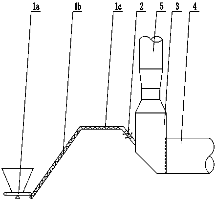
[0043] see figure 1 , the present embodiment is a kind of equipment based on the dry-process rotary kiln cement production line to co-process electrolytic manganese slag, mainly including quantitative feeder 1a, inclined screw conveyor 1b, horizontal screw conveyor 1c, air lock feeder 2, kiln tail Smoke chamber 3, rotary kiln 4, calciner 5. The discharge port of described quantitative feeder 1a is connected with the feed port of inclined screw conveyor 1b, and the discharge port of described inclined screw conveyor 1b is connected with the feed port of horizontal screw conveyor 1c, The discharge port of the horizontal screw conveyor 1c is connected with the feed port of the air lock feeder 2, and the discharge port of the described wind lock feeder 2 is connected with the feed port of the kiln tail smoke chamber 3 Communication, the flue gas outlet of the kiln tail smoke chamber 3 is connected with the air inlet of the calciner 5 through pipes, and the material outlet of the ...

Embodiment 2

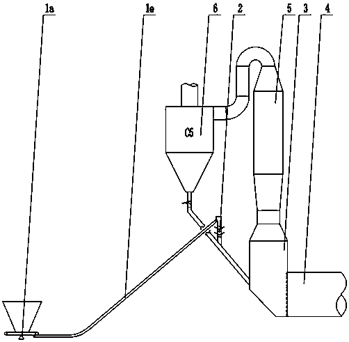
[0046] see figure 2 , a device based on the dry-process rotary kiln cement production line for co-processing electrolytic manganese slag, mainly including quantitative feeder 1a, belt conveyor 1e, air lock feeder 2, kiln tail smoke chamber 3, rotary kiln 4, decomposition Furnace 5, C5 level cyclone preheater 6. The discharge port of described quantitative feeder 1a is connected with the feed port of belt conveyor 1e, and the discharge port of described belt conveyor 1e is connected with the feed port of lock air feeder 2 , the discharge port of the air lock feeder 2 is connected with the lower end of the feeding pipe of the C5 grade cyclone preheater 6 (after the feeding pipe comes with a flap valve), and the C5 grade cyclone preheater The discharge port of the feeding pipe of 6 is connected with the feed port of the kiln tail smoke chamber 3, the air outlet of the kiln tail smoke chamber 3 is connected with the air inlet of the calciner 5 with a pipeline, and the kiln tail ...

Embodiment 3

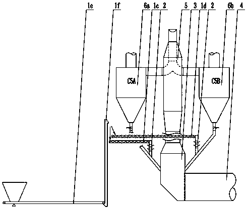
[0049] see image 3 , a device based on dry rotary kiln line co-processing electrolytic manganese slag, mainly including horizontal screw conveyor 1c, horizontal screw conveyor 1d, belt conveyor 1e, bucket elevator 1f, air lock feeder 2, Kiln tail smoke chamber 3, rotary kiln 4, calciner 5, C5A class cyclone preheater 6a, C5B class cyclone preheater 6b. The discharge port of the belt conveyor 1e is connected with the feed port of the bucket elevator 1f, and the discharge port of the bucket elevator 1f is connected with the horizontal screw conveyor 1c and the horizontal screw conveyor 1d respectively. The feed port of the horizontal screw conveyor 1c and the discharge port of the horizontal screw conveyor 1d are respectively connected with the feed port of the lock wind feeder 2, and the lock wind feeder corresponding to the horizontal screw conveyor 1c The first discharge port of the feeder 2 is connected with the lower end of the feeding pipe of the C5A-level cyclone prehea...


PUM


Abstract

The invention discloses a dry process rotary kiln cement production line based facility and method for cooperatively processing electrolytic manganese residues. The facility mainly comprises a rotarykiln, a kiln tail smoke chamber, a decomposition furnace, a manganese residue metering-delivering device, and a wind locking feeder. The discharge head end of the manganese residue metering-deliveringdevice is communicated with the feed inlet of the wind locking feeder. The discharge outlet of the wind locking feeder is communicated with the kiln tail smoke chamber. The kiln tail smoke chamber iscommunicated with a rotary chamber and the decomposition furnace. The invention also provides a method that utilizes the facility to process electrolytic manganese residues. The facility has a simplestructure, the technical process is short, the automatic control is easy, the investment is low, the processing amount is large, and the method is safe and environmentally friendly.

Description

technical field [0001] The invention relates to a treatment device and method for electrolytic manganese slag, in particular to a device and method for co-processing electrolytic manganese slag based on a dry rotary kiln production line. Background technique [0002] Electrolytic manganese slag is a neutral or weakly acidic waste residue produced by solid-liquid separation (press filtration) during the preparation of manganese electrolyte by acid leaching (combination) of manganese ore. At present, my country's electrolytic manganese production capacity has exceeded 2 million tons, and the amount of acid leaching waste slag discharged per ton of electrolytic manganese production is 5 to 7 tons, and the slag produced per ton of electrolytic manganese for lower-grade raw materials can reach 10 tons. The amount of burial reaches hundreds of millions of tons, and the annual increase reaches tens of millions of tons. The composition and properties of electrolytic manganese slag a...

Claims


Application Information

Patent Timeline
IPC IPC(8): C04B7/147C04B7/44F27B19/04F27D13/00
CPCC04B7/147C04B7/44C04B7/4407F27B19/04F27D13/00Y02P40/10
Inventor 尹小林
Owner 湖南省小尹无忌环境能源科技开发有限公司
Learn More