Preparation method of carbon nano-tube array and its application in preparing antenna array

A technology of carbon nanotubes and manufacturing methods, which is applied in the field of dipole antenna devices, can solve the problems of low efficiency, high price, unsuitability for large-scale research and application of nano-optoelectronic integrated devices, etc., and achieves simple preparation process, uniform diameter, improved Effect of Optical Signal Receiving Efficiency

Inactive Publication Date: 2007-04-18
王洋
View PDF0 Cites 15 Cited by
  • Summary
  • Abstract
  • Description
  • Claims
  • Application Information

AI Technical Summary

Problems solved by technology

[0002] The technology of using various metal wires as dipole antennas to transmit and receive low-frequency electromagnetic waves has a history of more than 100 years, while the research on optical frequency antennas is less than 50 years old
Even if it can be realized by electron beam lithography, its operating principle requires that each metal wire be fabricated one by one on the substrate, which is very expensive and has extremely low efficiency, which is very unsuitable for large-scale research and application of nano-optoelectronic integrated devices.

Method used


Image

  • Preparation method of carbon nano-tube array and its application in preparing antenna array
  • Preparation method of carbon nano-tube array and its application in preparing antenna array
  • Preparation method of carbon nano-tube array and its application in preparing antenna array

Examples


Embodiment 1

[0061] Example 1: Catalyst preparation

[0062] The substrate used to grow carbon nanotubes can be any solid material that can withstand the growth temperature (generally 300 ℃ ~ 500 ℃), including metals (or alloys), semiconductors (such as silicon), oxides (such as SiO 2 , ITO, ZnO, etc.) and polymer molecular materials (such as Polyimide), the above ITO refers to indium tin oxide: indium tin oxide. As shown in Figure 2, if a conductive substrate 2 such as metal or semiconductor is used, a layer of transition metal catalyst film 1 (such as iron, cobalt, nickel and their alloys) can be deposited directly on the surface of the substrate. The deposition method can be electrical Chemical deposition, thermal (or electron beam) evaporation deposition, sputtering deposition, and any other common metal thin film preparation methods in scientific research and industry. As shown in FIG. 2, if an insulating substrate 3 (such as glass, etc.) is used, a conductive layer 2 (such as chromium, t...

Embodiment 2

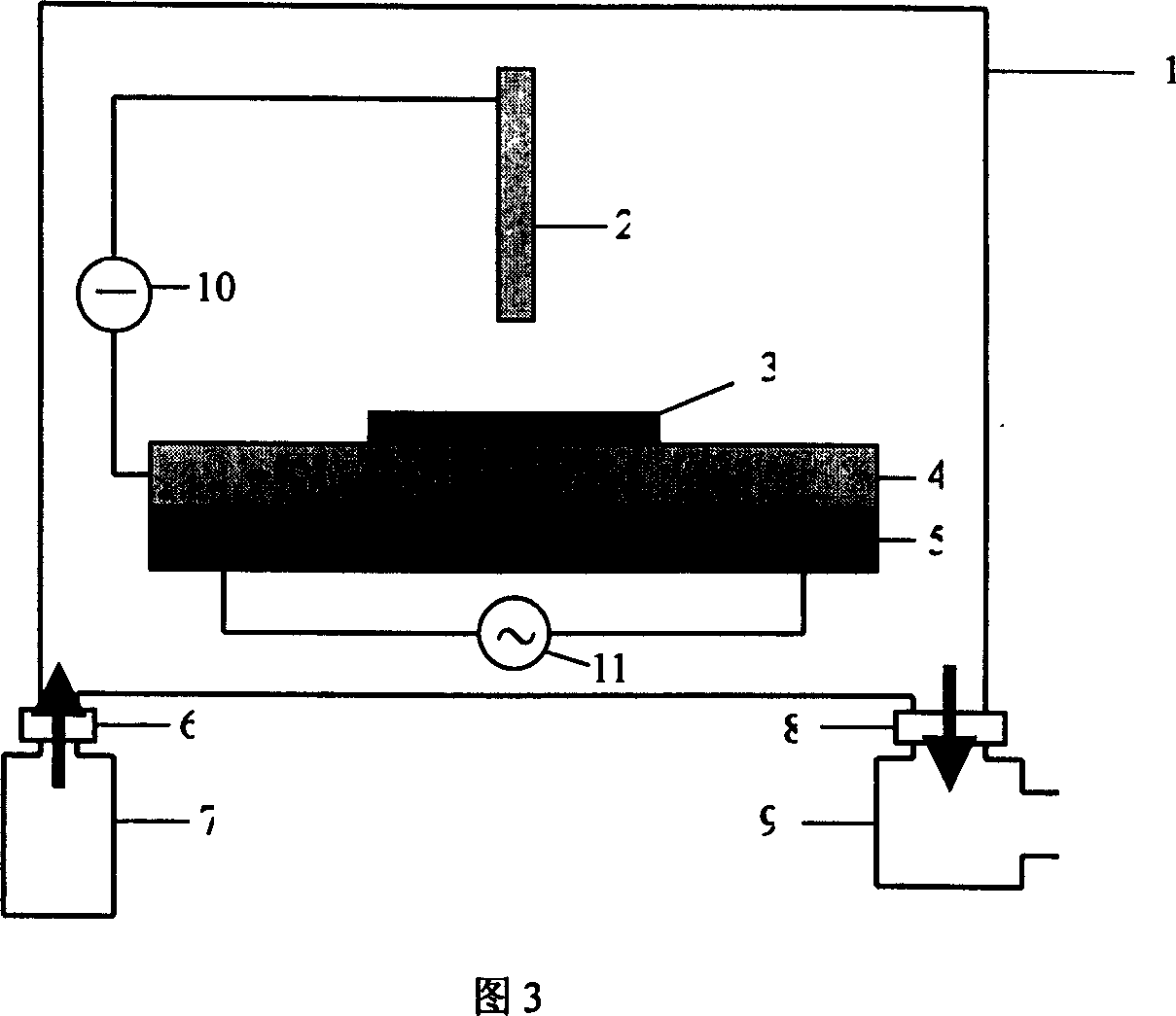
[0063] Embodiment 2: DC plasma chemical vapor deposition system structure

[0064] The growth of vertically aligned carbon nanotubes (fibers) can be accomplished by a direct current plasma chemical vapor deposition system. The basic structure of the system is shown in Figure 3. In the vacuum chamber 1', there are a vertical columnar electrode 2 and a horizontal disk electrode (i.e., a sample stage) 4. The distance between the two electrodes is about 1 to 3 cm, and they are tapped at both ends of the DC power supply 10. The shape of the vertical electrode 2 can also be a disc shape, a needle shape, etc., and its shape and size depend on actual conditions. The sample 3 to be grown is placed above the horizontal electrode (sample stage) 4, and the heater 5 can uniformly heat the electrode below. The heater can be connected to a standard AC power supply 11. Reactive gas (such as NH 3 And C 2 H 2 ) The gas source 7 passes through the flow rate adjusting valve 6 into the cavity. One end...

Embodiment 3

[0065] Example 3: Growth of vertically aligned carbon nanotube (fiber) array

[0066] After the sample is placed in the system, the air pressure in the chamber is pumped to 10 -2 Torr~10 -6 Torr is basically vacuum. Then turn on the heater power and gradually increase the temperature of the sample stage to 400℃~600℃, while passing in 160sccm NH 3 , And keep the system pressure to 1-20 Torr. After the temperature reaches the expected value and stabilizes, turn on the DC power supply and increase the voltage until a certain intensity of plasma is generated between the two electrodes. After a proper pre-etching time (generally no more than a few minutes), pass 20sccm~80sccm C 2 H 2 , To promote the vertical growth of carbon nanotube (fiber) array. The heating and plasma etching process causes the catalyst film to split into nanoparticles, thereby catalyzing the growth of carbon nanotubes (fibers). The length of carbon nanotubes (fibers) can be adjusted by controlling the growth time....


PUM

PropertyMeasurementUnit
lengthaaaaaaaaaa
diameteraaaaaaaaaa
strengthaaaaaaaaaa

Abstract

The present invention relates to a carbon nano tube array, its preparation method and application in preparation of optical frequency dipole antenna array. The invented carbon nano tube optical frequency dipole antenna array is characterized by that the carbon nano tubes are perpendicular to the substrate material and arranged, the length and diameter ratio of carbon nano tube of fibre is greater then 10. The method for making the carbon nano tube array is characterized by that it uses transition metal film catalyst to regulate its thickness, and utilizes plasma chemical gas phase deposition system to regulate plasma energy density and distribution, controls reaction time, gas pressure and gas flow speed ratio so as to implement large-area perpendicular growth of carbon nano tube or fibre array on various substrates at lower temperature and accurately control length and diameter of produced carbon nano tube or fibre.

Description

Technical field [0001] The present invention relates to a dipole antenna device for transmitting and receiving optical frequency electromagnetic waves (light waves) in the technical field of nano-photoelectric materials and devices, and more specifically to a carbon nanotube array and carbon nanofiber array (hereinafter referred to as carbon nanotubes). Array), its preparation method and its application in preparing antenna array or preparing optical frequency dipole antenna array. Or the application of vertically arranged carbon nanotube arrays in the preparation of optical frequency dipole antenna arrays. Background technique [0002] The technology of using various metal wires as dipole antennas to transmit and receive low-frequency electromagnetic waves has a history of more than one hundred years, and the research on optical frequency antennas has been less than 50 years. The mechanism is that for the receiving antenna, by adjusting the effective length of the antenna to be ...

Claims


Application Information

Patent Timeline
Patent Type & Authority Applications(China)
IPC IPC(8): C01B31/02B82B1/00H01Q21/00
Inventor 王洋
Owner 王洋
Why Eureka
Try Eureka