
Method of manufacturing a spectral filter for green and shorter wavelengths

a manufacturing method and technology for spectral filters, applied in the field of optical filters, can solve the problems of poor optical performance, limited physical longevity, and disadvantages of prior art optical filters and/or coating constructions, and achieve the effects of reducing manufacturing complexity, and improving the quality of spectral filters

Inactive Publication Date: 2004-03-11
LAKE SHORE CRYOTRONICS INC
View PDF15 Cites 43 Cited by
  • Summary
  • Abstract
  • Description
  • Claims
  • Application Information

AI Technical Summary

Benefits of technology

[0014] One way to protect these sensitive multilayer optical coatings is to embed them into a transparent epoxy by lamination onto other glass substrates. However, optical filters made by a soft or hard film deposition may include multiple coating layers and laminations, requiring cumbersome and relatively costly manufacturing processes. Moreover, the epoxy laminate can sometimes effectively limit the useful temperature range of the product, typically to less than about 100.degree. C. Epoxies can also discolor and degrade over a short time period when exposed to ultraviolet radiation, rapidly degrading the filters' optical performance. Additionally, epoxy laminates may tend to autofluoresce upon exposure to UV radiation. These effects can limit the use of such laminates in sensitive, critical instrumentation and other sensitive applications requiring long-term and / or high stability and high temperature range.
[0158] By following the spectral filter manufacturing steps disclosed herein, functional spectral filters can be produced. Such filters can be used at ultraviolet or shorter wavelengths, for instance, in vacuum or low moisture atmospheres. Operation of such a filter under high humidity conditions can encounter difficulties. These problems may be caused by the porous structure of the filter, known to be prone to absorbing moisture from the atmosphere below the dew point because of the high surface area and capillary-sized pores. In order to provide a viable commercial product, encapsulation of the filter layer in an optically and / or chemically compatible manner that will protect it from contaminants in the atmosphere may be required at times. Special care during the choice of the encapsulation method must be taken to avoid autofluorescence from the encapsulating material.

Problems solved by technology

As the wavelength of light becomes shorter in the ultraviolet range, however, certain prior art optical filter and / or coating construction suffers from disadvantages such as for example:
poor optical performance,
limited physical longevity,
poor imaging quality of transmitted radiation, and / or
transmitted wavelength instability.
Such films are generally soft and lack physical durability.
Some such coatings also may contain refractory metal oxides that are in general more durable, but standard oxide coatings are generally optically unstable when exposed to a varying environment (e.g., temperature and humidity).
However, optical filters made by a soft or hard film deposition may include multiple coating layers and laminations, requiring cumbersome and relatively costly manufacturing processes.
Moreover, the epoxy laminate can sometimes effectively limit the useful temperature range of the product, typically to less than about 100.degree. C.
Epoxies can also discolor and degrade over a short time period when exposed to ultraviolet radiation, rapidly degrading the filters' optical performance.
Additionally, epoxy laminates may tend to autofluoresce upon exposure to UV radiation.
These effects can limit the use of such laminates in sensitive, critical instrumentation and other sensitive applications requiring long-term and / or high stability and high temperature range.
Soft film filters can be vulnerable to abrasion and can be sensitive to temperature and humidity and therefore may have relatively limited operating lifetimes. Additionally, any laminates will generally degrade the ability to image through a filter of this type, significantly limiting their application.
However, MDM films are often soft and easily damaged by moisture and oxygen.
This construction is expensive and heavy.
However, the optical performance of MDM filters is often rather limited.
For example, they are relatively rugged (they generally consisted of a single piece of perforated metal); relatively lightweight, compact, and relatively insensitive to environmental factors such as heat and humidity.
Unfortunately, techniques used for the manufacture of such metallic waveguide-based IR optical filters generally cannot be extended easily into the near-infrared, visible, and UV spectral regions.
This can be difficult to accomplish as a practical matter in machined metal.
However, this fabrication process may result in a general lack of control of the shape of the transmission spectrum.
In particular, the transition from full transmission to full blocking of such filters in the UV range can take up to more than a hundred nm in wavelength, which is not acceptable for many practical applications.
A sharper transmission edge can be achieved by increasing of the aspect ratio, but this may result in strong degradation of overall transmission efficiency.
Another drawback of the glass microchannel approach includes the lack of control over the uniformity of channel sizes, leading to even wider transmission edges (resulting in degradation of the transmitted image quality) and channel wall smoothness (resulting in even stronger losses within the pass-band).
However, the method of removing the macroporous layer from the Si wafer, as disclosed in U.S. Pat. No. 5,262,021, will result in the second surface of the macroporous layer being inherently rough, causing high losses due to scattering.
While such filters exhibit some short-pass filtering, the transmission spectral shape through them will be unusable for commercial applications due to the wide blocking edge.
However, in such disclosures, the MPSi layer is not freestanding, i.e. a substantial portion of the silicon wafer is left under the porous layer, thus making such a structure completely opaque and non-functional in the UV and visible spectral ranges.
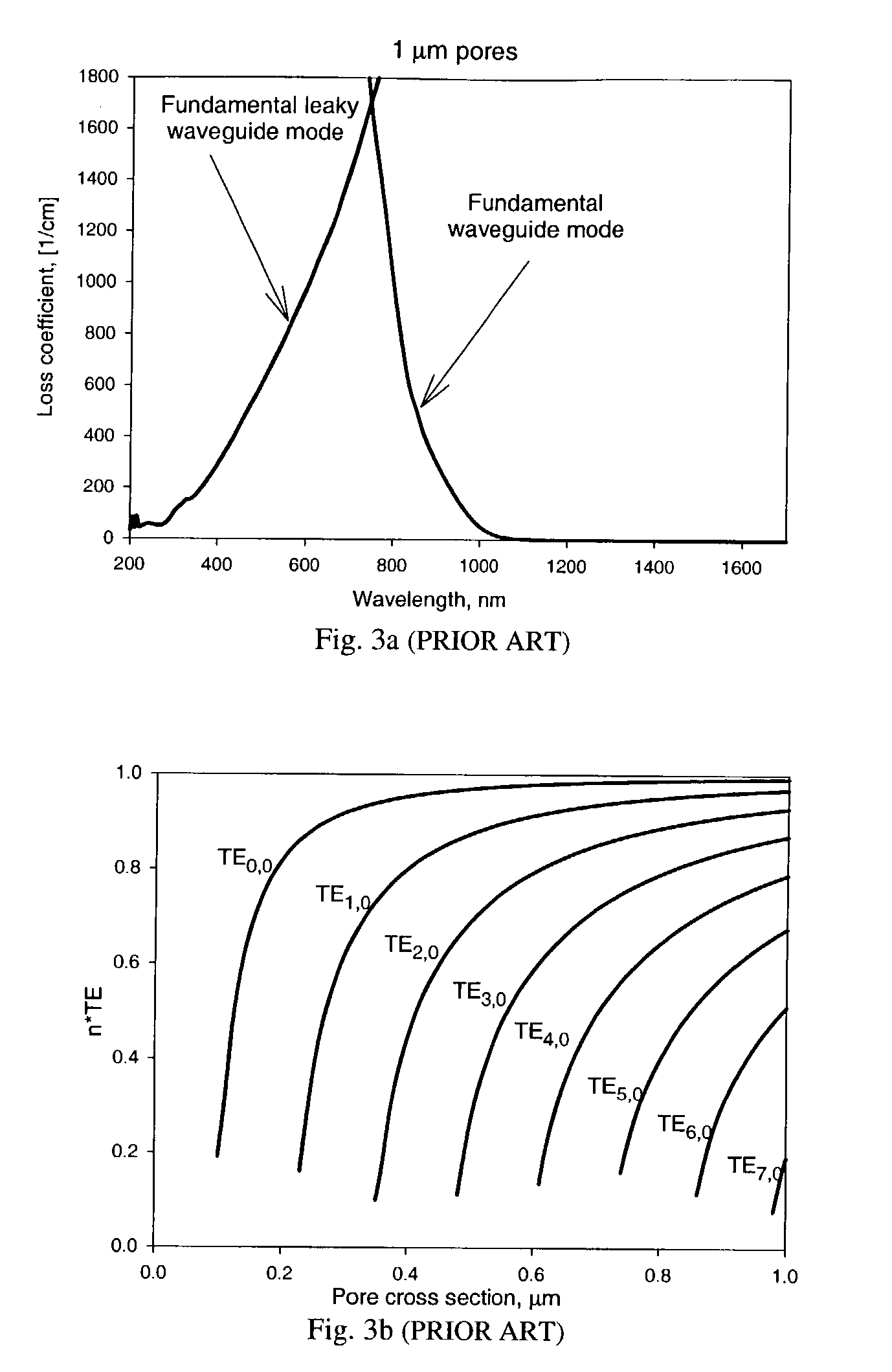
This means that the transmission through the MPSi filter takes place not through one leaky waveguide mode, but rather through a number of leaky waveguide modes.
In the far field, the destructive and constructive interference of all light sources in the form of leaky waveguide or waveguide ends takes place.
However, some applications are not sensitive to the outcoupling of light to higher diffraction orders, for instance, when the filter is directly mounted on the top of a photodetector or a detector array.
In other cases, the main source of outcoupling losses is the redistribution of light into higher diffraction orders.
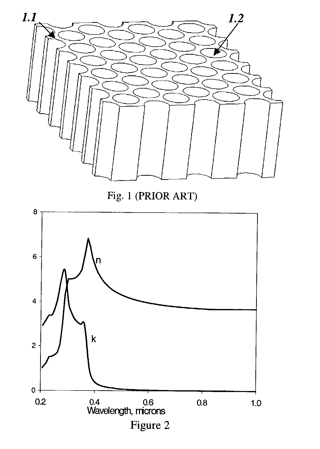
The exemplary prior art spectral filter structure of FIG. 1 is disadvantageous from the viewpoint of the wide transition from the pass band of the spectral filter to the blocking band, referred to herein as "blocking edge".
Modifications of pore diameter d and MPSi thickness t of the prior art structure of FIG. 1 cannot solve this problem, since increasing t while keeping d constant or decreasing d while keeping t constant leads to some narrowing of the transmission edge, but this is accomplished at the expense of strong degradation of filter transmission efficiency and an unavoidable shift of the blocking edge to shorter wavelengths, which is clearly unacceptable.
Although stripped MPSi layers according to the disclosed method can be used as functional short-pass filters (with the drawbacks, disclosed previously), the optical quality of the second surface of the MPSi layer is quite poor (due to inherent roughness) and thus this prior art method is disadvantageous in some aspects.
However, the MPSi layer quality obtained by using this method is of generally poor optical quality with strong pore wall erosion and branching.
It may be that no spectral filter technology has yet been demonstrated in any porous semiconductor material other than silicon.
For example, freestanding macroporous semiconductor layers, which are useful for ultraviolet filter, have not been demonstrated in materials other than silicon.
Despite of the fact that pore filling in anodic alumina by metals or semiconductors has been widely employed, the coating of pore walls for use as optical filters has not been attempted or taught.
This may, however, limit the pass band of the filter to the transparency range of the pore filling material (for example to 150 nm for silicon dioxide or 200-300 nm for some polymers).
Such filters are useful for a wide variety of applications, including applications where currently available filter systems cannot provide acceptable performance.
In contrast, prior art filters may exhibit significant autofluorescence, such as resulting from the required epoxy lamination of such filters, and such autofluorescence can render the analysis system unreliable or even practically inoperable.
The suppression of the reflection of leaky waveguide modes from the pore walls causes the high and relatively narrow peak of losses centering at said wavelengths inside the initial blocking edge.
The number of layers used will be determined by the particular application requirements of the filter and can be arbitrarily large, limited only by the economic or process requirements.
Operation of such a filter under high humidity conditions can encounter difficulties.
These problems may be caused by the porous structure of the filter, known to be prone to absorbing moisture from the atmosphere below the dew point because of the high surface area and capillary-sized pores.

Method used


Image

  • Method of manufacturing a spectral filter for green and shorter wavelengths
  • Method of manufacturing a spectral filter for green and shorter wavelengths
  • Method of manufacturing a spectral filter for green and shorter wavelengths

Examples


example 2

[0162] The method in Example 1 was repeated but improved by increasing the smoothness of the pore walls (reducing the optical scattering). To suppress the roughness, the SiO.sub.2 layer was etched off the pore walls in HF (5 minutes in 48% aqueous solution under agitation). The wafer was then cleaned in de-ionized water for 5 minutes and was placed into the hot tube furnace (1000.degree. C.) for 2 hours a second time to re-form a layer of silicon dioxide on the pore walls. A functional short-pass filter consisting of a free-standing MPSi layer with about 120 nm of SiO.sub.2 covering the smoothed pore walls was thus formed.

example 3

[0163] In a third example, a p-doped double-side polished (100) higher-resistivity Si wafer, a different electrolyte and a long-wavelength suppression layer applied to the second surface of the MPSi layer were used. The resistivity was in the 67.9-73 Ohm*cm range as measured by the vendor. The wafer was oxidized in the hot tube (1000.degree. C.) for 4 hours, producing 200 nm of oxide on all surfaces of the silicon. The wafer was photolithographically patterned from the first side of the wafer (i.e. holes in a photoresist layer were formed at the predetermined locations). The pattern was of cubic symmetry with round holes spaced 5 microns apart and having diameters of 2.5 microns. In this example, the axes of the pattern were oriented parallel to the crystallographic axes of the silicon wafer. The photoresist pattern was transferred into the SiO.sub.2 layer through a reactive ion etching process. The subsequent etch pit formation and anodization steps were the same as in Example 1, e...

example 4

[0164] In this example, the steps of Example 1 were followed except a lower resistivity wafer and a different electrolyte composition were used and mechanical removal of the unwanted silicon in the pore array area was employed. The resistivity was in the 20-40 Ohm*cm range as measured by the vendor. The electrolyte had the composition 1[HF]+2 [Ethanol]+12 [DMF] by volume. After the pores were etched and the gold removed, the wafer was mechanically polished from the back side until the porous layer was reached. During this process, the wafer was waxed by its first surface to a glass 2.times.2 inch wafer to provide mechanical support for the MPSi layer during the polishing step. After the unwanted silicon was removed, the wafer was then placed into acetone for 6 hours to strip it from the glass plate. The wafer was cleaned in multiple fresh rinses of acetone to completely remove remaining wax. The oxidation step was then performed, providing a functional short-pass filter consisting o...


PUM

PropertyMeasurementUnit
thicknessaaaaaaaaaa
thicknessaaaaaaaaaa
temperatureaaaaaaaaaa

Abstract

The UV, deep UV and / or far UV (ultraviolet) filter transmission spectrum of an MPSi spectral filter is optimized by introducing at least one layer of substantially transparent dielectric material on the pore walls. Such a layer will modify strongly the spectral dependences of the leaky waveguide loss coefficients through constructive and / or destructive interference of the leaky waveguide mode inside the layer. Increased blocking of unwanted wavelengths is obtained by applying a metal layer to one or both of the principal surfaces of the filter normal to the pore directions. The resulting filters are stable, do not degrade over time and exposure to UV irradiation, and offer superior transmittance for use as bandpass filters. Such filters are useful for a wide variety of applications including but not limited to spectroscopy and biomedical analysis systems.

Description

CROSS-REFERENCES TO RELATED APPLICATIONS[0001] This application claims the benefit of priority from provisional application No. 60 / 384,850 filed Jun. 4, 2002 (attorney docket no. 340-66), incorporated herein by reference. This application is related to commonly-assigned copending application Ser. No. ______ of Kochergin filed Jun. 4, 2003 entitled "Spectral Filter For Green and Shorter Wavelengths" (attorney docket no. 340-75) also incorporated herein by reference.[0002] Not applicable.FIELD[0003] The technology herein relates to optical filters and to methods of fabricating optical filters, and more specifically to ways to make optical filters constructed of artificially structured materials. Still more particularly, the technology herein relates to violet, ultraviolet, deep ultraviolet and far ultraviolet optical filters having significantly improved optical performance, manufacturability, extended physical longevity, transmitted wavelength stability, minimal autofluorescence and ...

Claims


Application Information

Patent Timeline
Patent Type & Authority Applications(United States)
IPC IPC(8): G02B5/20G02B5/22G02B6/122
CPCB82Y20/00G02B5/201G02B5/204G02B5/207G03F7/70958G02B5/22G02B6/1225G03F7/70575G03F7/70941G02B5/208
Inventor KOCHERGIN, VLADIMIRSWINEHART, PHILIP
Owner LAKE SHORE CRYOTRONICS INC
Learn More