Apparatus and method for point-of-use treatment of effluent gas streams

a technology of effluent gas and apparatus, which is applied in the direction of perfluorocarbon/hydrofluorocarbon capture, crystal growth process, separation process, etc., can solve the problems of high energy consumption, high temperature heated modules may accelerate corrosion downstream of thermal modules, and generation of nox resulting from ammonia oxidation, etc., to achieve high efficiency

Inactive Publication Date: 2004-10-28
APPLIED MATERIALS INC
View PDF25 Cites 79 Cited by
  • Summary
  • Abstract
  • Description
  • Claims
  • Application Information

AI Technical Summary

Benefits of technology

0039] It is a further object of the present invention to provide an effluent gas treatment system that employs a water scrubber in a highly efficient manner.

Problems solved by technology

Disadvantages of thermal oxidation include (i) high energy consumption, and (ii) the generation of NOx resulting from the oxidation of ammonia.
In addition, high temperature heated modules may accelerate corrosion downstream of the thermal module because the acid gases (F.sub.2 and HF) are heated, but not abated in the thermal unit.
It is in the hot, moist interface region between the water scrubbing unit and the thermal unit that the hot acid gases typically cause corrosion.
Existing non-optimized conditions in the semiconductor manufacturing process result in PFC utilization that varies depending on the specific gas and process used.
High PFC conversions inevitably result in the formation of hazardous air pollutants (HAPs).
These estimates represent worse case scenarios and do not account for the short duration and periodic nature of processes using PFCs, the lower concentrations of F.sub.2 emissions during initial cleaning stages, and the reduced probability that two or more chambers run PFC cycles synchronized.
Nonetheless, such estimates indicate the serious and worsening character of the PFC problem associated with semiconductor manufacturing operations.
The toxic and corrosive nature of fluorinated HAPs pose considerable health and environmental hazards in addition to jeopardizing the integrity of exhaust systems.
The main challenges to this potential approach are heat dissipation and forming acceptable by-products.
This last condition could be a limiting factor especially when large volumes of F.sub.2 are involved.
The removal efficiencies in these post-reaction water scrubber beds are often compromised, inasmuch as the scrubbing efficiency of most acid gases decrease as a function of temperature.
In addition, containment of hot concentrated acids requires expensive materials and construction to prevent temperature-enhanced corrosion attack.
Objections to using water scrubbers include concerns over the formation of unwanted OF.sub.2, and the water consumption necessary to achieve acceptable removal efficiencies at high fluorine challenges.
Water scrubbing removal of silanes has generally not been considered advantageous in comparison to thermal oxidation, because of the very low solubility of silanes in water and their very low reactivity with water.
The prior art in some instances has used chemicals such as KOH and NaOH for such scrubbing, but scrubbing silanes with such hydrides generally requires large amounts of the chemical additives and therefore entails substantial operating costs.
These devices, however, suffer from the disadvantage of requiring ignition sources and fuel, or alternatively electricity, for heating.
The associated process also tends to be highly exothermic in nature, resulting in excessive temperatures and substantial exhaust gas quenching requirements.
Another problem experienced in abatement of silanes is that ammonia gas may also be present in the effluent gas stream.
The concurrent presence of silane and ammonia presents particular difficulty in achieving high levels of abatement of these components.
A further problem that has plagued the use of water scrubbers for the treatment of effluent gas streams is foaming.
In certain semiconductor applications, effluent gases can cause foam formation when entering a water scrubber and such foam can cause deleterious effects inside the scrubber.
The most serious problem occurs when the foam builds up in such a large quantity as to completely fill the interior volume of the scrubber.
Where the foam coalesces on the exhaust pipe surfaces, corrosion can occur.
Additionally, foaming can cause cavitation when foam is present in the sump liquor of the scrubber, and the foam thereby can damage the pump that recirculates the scrubbing liquor.
Finally, such foaming activity may significantly increase the pressure drop across the scrubber and thereby adversely affect the operation not only of the scrubber and effluent treatment system, but also the operation of upstream semiconductor manufacturing units that are pressure-sensitive in character.
Yet another problem encountered in the operation of water scrubbers for effluent gas treatment is the mineralic content of the water used in the scrubber.
This creates a number of problems.
This can cause the pump to seize up and fail.
Another problem is that the CaCO.sub.3 deposits build up on the packing surfaces of the scrubber.
This in turn causes an increase in pressure drop across the scrubber and a decrease in scrubbing efficiency.
Finally, CaCO.sub.3 deposits may form in the water lines of the scrubber, causing an increase in pressure drop and therefore a reduction in water flow rate.
Another solids deposition problem of a more general character is the clogging by solids of lines connected to pressure sensing devices in the abatement system.
If solids build up in the sensing line, the reading of the associated pressure sensing device will be inaccurate and may give a false alarm signal causing the abatement system to be shut down.
A related problem is the occurrence of solids deposition in the entry to the water scrubber, which may be attributable to the presence of condensable gases in the effluent gas stream being processed.
On the other hand, the water at the gas outlet of a column operated in cocurrent fashion (column bottom) can be saturated with the given acid gas, thereby limiting the scrubbing potential.
Unfortunately, the column size, packing wetting requirements, and effective solids removal demand that a significant water flow rate must pass over the packing in either cocurrent or countercurrent operation.
Using such a high flow rate of fresh water is undesirable in terms of cost and also due to the significant consumption of water by the process facility, particularly in regions where water is scarce.
However, recirculation decreases the scrubbing efficiency of the scrubber for the aforementioned gas species.
However, the use of chemical agents in this approach is costly and can present additional safety concerns.

Method used


Image

  • Apparatus and method for point-of-use treatment of effluent gas streams
  • Apparatus and method for point-of-use treatment of effluent gas streams
  • Apparatus and method for point-of-use treatment of effluent gas streams

Examples


example 1

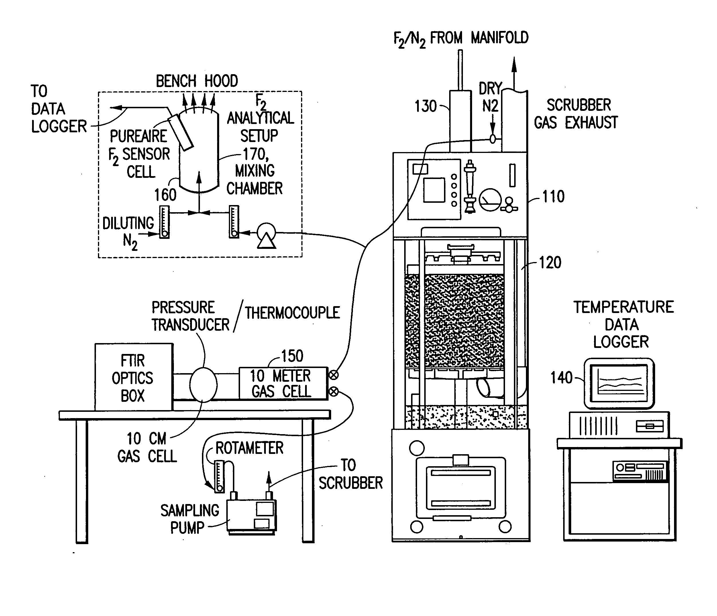
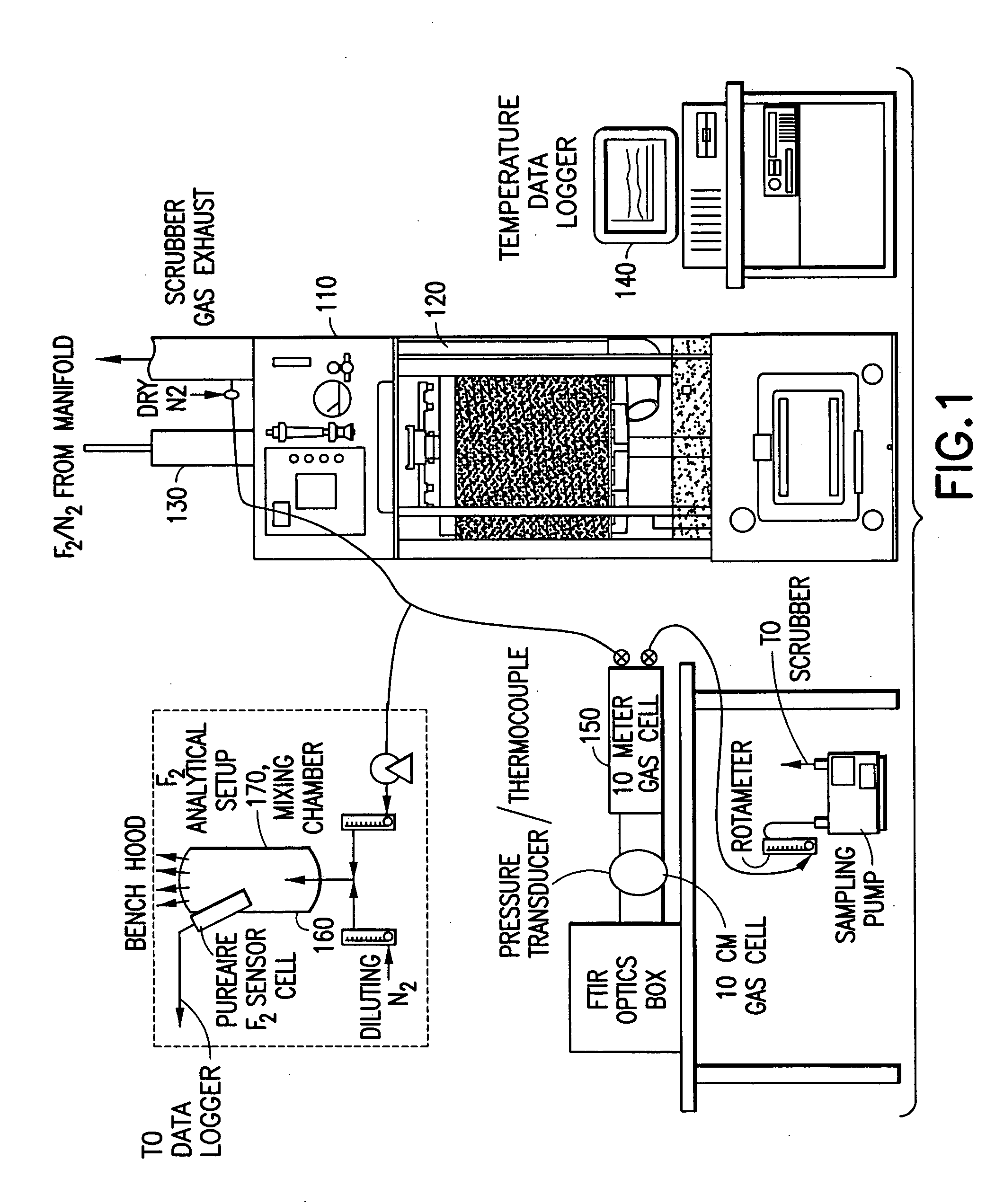
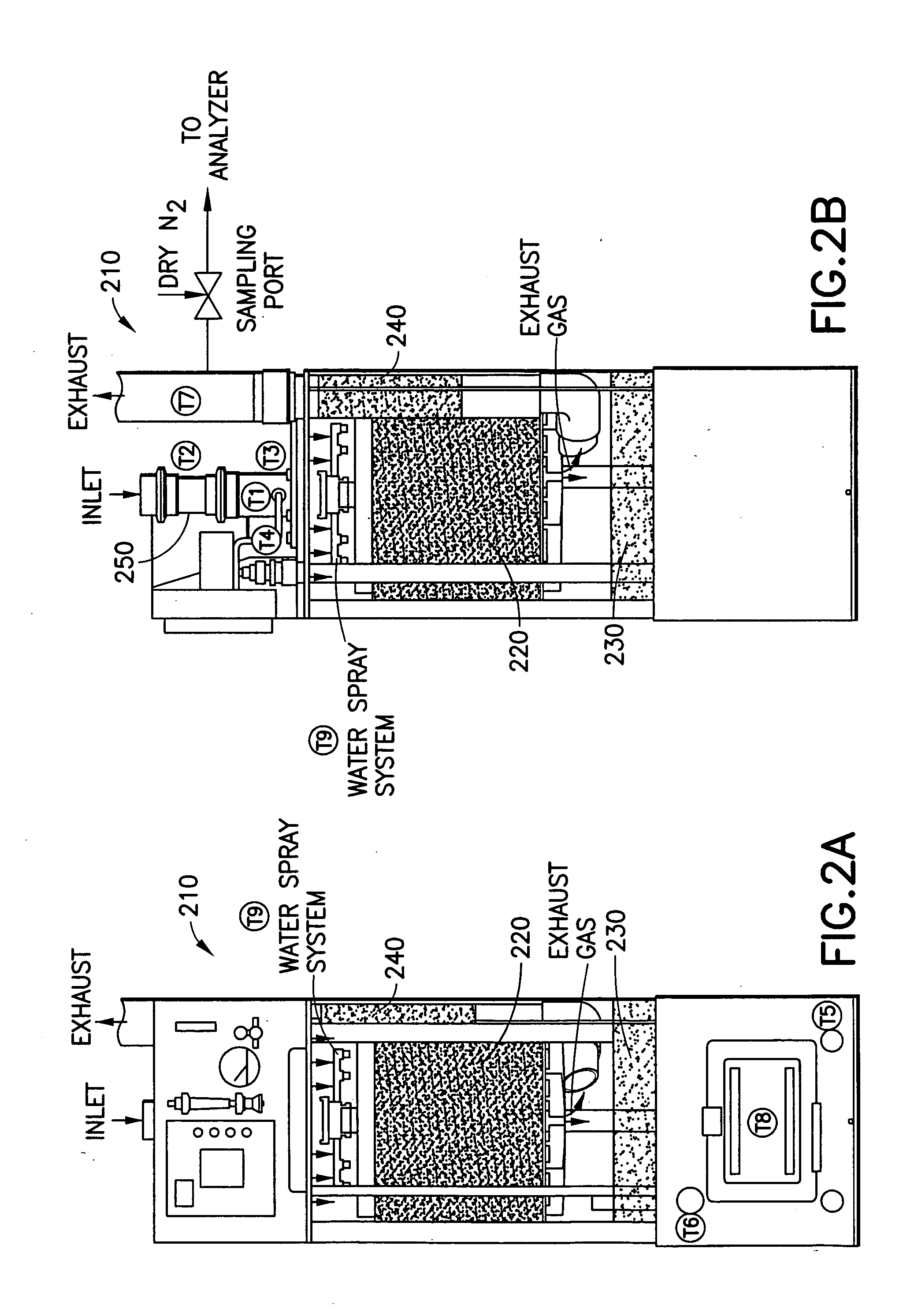
[0171] In a system of the general type shown in FIGS. 1 and 2, abatement of SiF.sub.4 was carried out using an effluent stream simulating effluent produced in a semiconductor manufacturing facility by cleaning of plasma reaction chambers.

[0172] Table 1 below summarizes results for the abatement (destruction and removal efficiency, % DRE) of SiF.sub.4, with and without the injection of caustic. The abatement in this instance did not include the introduction of a reducing agent.

[0173] Fixed concentrations (300 ppm) of silicon tetrafluoride balanced with 120 slpm of nitrogen were introduced into the water scrubber. The experimental conditions were chosen to represent or exceed effluent gas concentrations released during typical plasma chamber cleans. Abatement efficiencies were measured as a function of water flow rates (0.5 and 1 gpm), and scrubber pH (with and without caustic injection). In all cases investigated, measured scrubber outlet concentrations of HF and SiF.sub.4 were sligh...

example 2

[0174] Fluorine gas flow rates ranging between 0.5 to 5 slpm were delivered into a Vector.RTM.-100 water scrubber (ATMI Ecosys Corporation, San Jose, Calif.) that was equipped with a passivated manifold. These streams were diluted with 50 slpm of balanced nitrogen resulting in challenges between 1 and 6% F.sub.2. In addition, the effects of residence time within the scrubber were studied by increasing the nitrogen flow rate to 200 slpm. The performance of the scrubber unit was tested using standard (1.2 gpm) and low (0.75 gpm) water flow rates. Sodium thiosulfate was used during high fluorine gas challenges to improve fluorine gas removal and to eliminate the formation of OF.sub.2 as a by-product.

[0175] Table 2 summarizes the experimental data, and illustrates the enhancement achieved by injection of sodium thiosulfate as a reducing agent.

2TABLE 2 Summary of Fluorine Abatement Results OF2 Water N2 F2 Flow HF Out. F2 Out. Out. Outlet F2 Flow Balance Rate F2 inlet Chem. Conc. Conc. Co...


PUM

PropertyMeasurementUnit
temperaturesaaaaaaaaaa
temperatureaaaaaaaaaa
flow rateaaaaaaaaaa

Abstract

A system for abating undesired component(s) from a gas stream containing same, such as halocompounds, acid gases, silanes, ammonia, etc., by scrubbing of the effluent gas stream with an aqueous scrubbing medium. Halocompounds, such as fluorine, fluorides, perfluorocarbons, and chlorofluorocarbons, may be scrubbed in the presence of a reducing agent, e.g., sodium thiosulfate, ammonium hydroxide, or potassium iodide. In one embodiment, the scrubbing system includes a first acid gas scrubbing unit operated in cocurrent gas/liquid flow, and a second "polishing" unit operated in countercurrent gas/liquid flow, to achieve high removal efficiency with low consumption of water. The scrubbing system may utilize removable insert beds of packing material, packaged in a foraminous containment structure. The abatement system of the invention has particular utility in the treatment of semiconductor manufacturing process effluents.

Description

[0001] This is a continuation-in-part of U.S. patent application Ser. No. 09 / 086,033 filed May 28, 1998 in the name of Jose I. Arno for "Apparatus and Method for Point-of-Use Abatement of Fluorocompounds," and is also a continuation-in-part of U.S. patent application Ser. No. 08 / 857,448 filed May 16, 1997 in the names of Joseph D. Sweeney, et al. for "Clog-Resistant Entry Structure for Introducing Particulate Solids-Containing and / or Solids-Forming Gas Stream to a Gas Processing System."BACKGROUNDS OF THE INVENTION[0002] 1. Field of the Invention[0003] This invention relates generally to abatement of undesirable components such as fluorine, silane, gaseous fluorides, acid gases, hydride gases and halide gases from effluent streams containing same, and more specifically to the use of systems employing a wet scrubber apparatus and method for abating undesirable components of the aforementioned type in semiconductor manufacturing processes.[0004] 2. Description of the Related Art[0005]...

Claims


Application Information

Patent Timeline
Patent Type & Authority Applications(United States)
IPC IPC(8): B01D19/04B01D45/00B01D53/14B01D53/68B01D53/70B01D53/78B01J4/00B01J4/04B01J8/00B01J8/20B01J8/22B01J19/00B01J19/26C23C16/44C30B25/14
CPCB01D19/04B01D45/00B01D53/14B01D53/68B01D53/70B01D53/78B01J4/001B01J4/04B01J8/003B01J8/20B01J8/22B01J19/002B01J19/26B01J2219/00065B01J2219/00094B01J2219/00135B01J2219/00164B01J2219/00252B01J2219/00268C23C16/4412C30B25/14Y02C20/30B01D2257/553B01D2258/0216
Inventor ARNO, JOSE I.HOLST, MARKYEE, SAMSWEENEY, JOSEPH D.LORELLI, JEFFDESEVE, JASON
Owner APPLIED MATERIALS INC
Why Eureka
Try Eureka