Hole transport layer compositions and related diode devices

Active Publication Date: 2005-07-07
NORTHWESTERN UNIV
View PDF9 Cites 57 Cited by
  • Summary
  • Abstract
  • Description
  • Claims
  • Application Information

AI Technical Summary

Benefits of technology

[0021] Accordingly, this invention can utilize a siloxane crosslinking approach to robust, efficient, adherent HTLs for PLEDs. Certain embodiments, for example, can employ 4,4′-bis[(p-trichlorosilylpropylphenyl)phenylamino]biphenyl (i.e., TPDSi2 or e.g., the corresponding monosilylated, i.e., TPDSi, and trisilylated, i.e., TPDSi3 compounds), which combines the hole-transporting efficiency of N,N-diphenyl-N,N-bis(3-methylphenyl)- 1,1-biphenyl)-4,4-diamine) (TPD, a representative small-molecule HTL material) and the strong crosslinking/densification tendencies of organosilanyl groups, to condense with available substrate functionalities (e.g., hydroxy) and/or provide either a cross

Problems solved by technology

For polymer-based LEDs (PLEDs), while single-layer polymer devices have obvious attractions such as ease of fabrication and large carrier mobilities, their performance is limited by inefficient hole injection from the ITO anode into the HOMO level of the EML polymer, as a result of, among other factors, the ITO work function (4.7 eV) and EML HOMO level (5.3-5.9 eV) mismatch.
Compared to its small-molecule counterparts, a multilayer PLED device is far more challenging to fabricate due to the risk of p

Method used


Image

  • Hole transport layer compositions and related diode devices
  • Hole transport layer compositions and related diode devices
  • Hole transport layer compositions and related diode devices

Examples


example 1

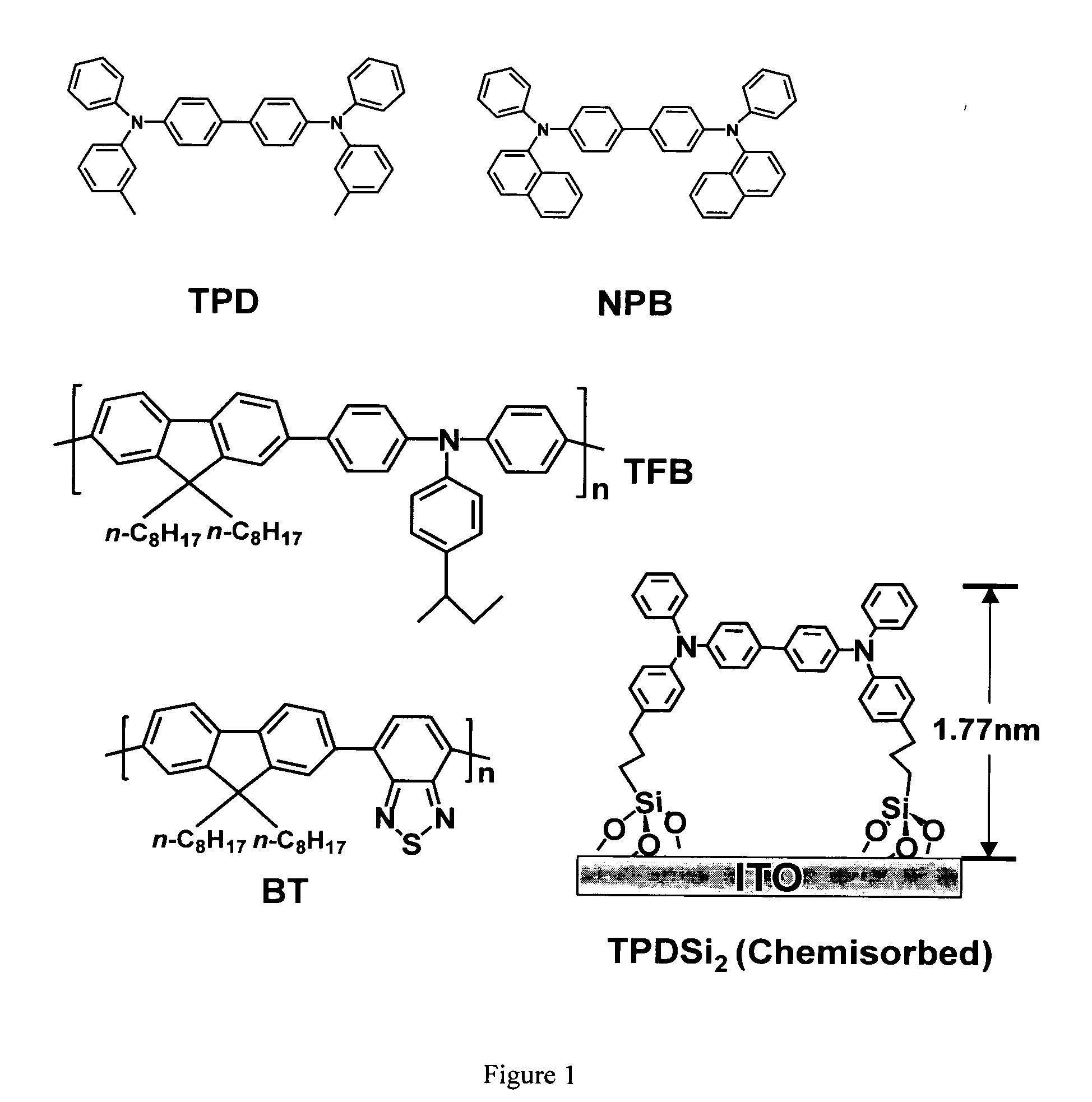
[0049] Synthesis of Poly(9,9-dioctylfluorene-co-N-(4-(3-methylpropyl))diphenylamine) (TFB). TFB was synthesized from 2,7-bis(4,4,5,5-tetramethyl-1,3,2-dioxaborolan-2-yl)-9,9-dioctylfluorene and 4-(3-methylpropyl)-N,N-bis(4-bromophenyl)aniline using conventional Suzuki coupling methodology and procedures similar to those described in the literature. The reagents 2,7-bis(4,4,5,5-tetramethyl-1,3,2-dioxaborolan-2-yl)-9,9-dioctylfluorene and 4-(3-methylpropyl)-N,N-bis(4-bromophenyl)aniline were synthesized using procedures also described in literature. Experimental details are as follows.

[0050] To a mixture of purified 4-(3-methylpropyl)-N,N-bis(4-bromophenyl)aniline (0.459 g, 1.0 mmol) and 2,7-bis(4,4,5,5-tetramethyl-1,3,2-dioxaborolan-2-yl)-9,9-dioctylfluorene (0.642 g, 1.0 mmol) in 10 mL oxygen-free toluene under nitrogen was added 0.1 g (0.25 mmol) of the phase transfer catalyst “Aliquat 336” and 6 mL of 2 M aqueous Na2CO3 solution (the Na2CO3 solution was purged with N2 for 10 min ...

example 2

[0051] Synthesis of Poly(9, 9-dioctylfluorene-co-benzothiadiazole) (BT). BT was synthesized from 2,7-bis(4,4,5,5-tetramethyl- 1,3,2-dioxaborolan-2-yl)-9,9-dioctylfluorene and 4,7-dibromo-2,1,3-benzothiadiazole using conventional Suzuki coupling methodology and procedures similar to those described in the literature. The reagent 4,7-dibromo-2,1,3-benzothiadiazole was synthesized using a procedure also described in the literature. Experimental details are described as follows.

[0052] Under inert atmosphere, a 50 mL reaction flask was charged with 0.15 g (0.51 mmol) of purified 4, 7-dibromo-2, 1, 3-benzothiadiazole and 3 mL oxygen-free THF. Next, the 4, 7-dibromo-2, 1, 3-benzothiadiazole mixture was brought to ˜60° C. with stirring, at which point the benzothiadiazole dissolved. Bis(tetraethylammonium) carbonate (1.0 g 3.0 mol) in 2 mL de-ionized water was purged with N2 gas for 10 min and then added to the reaction flask, and the mixture was stirred under N2 for 10 min. Next, 2,7-bis(...

example 3

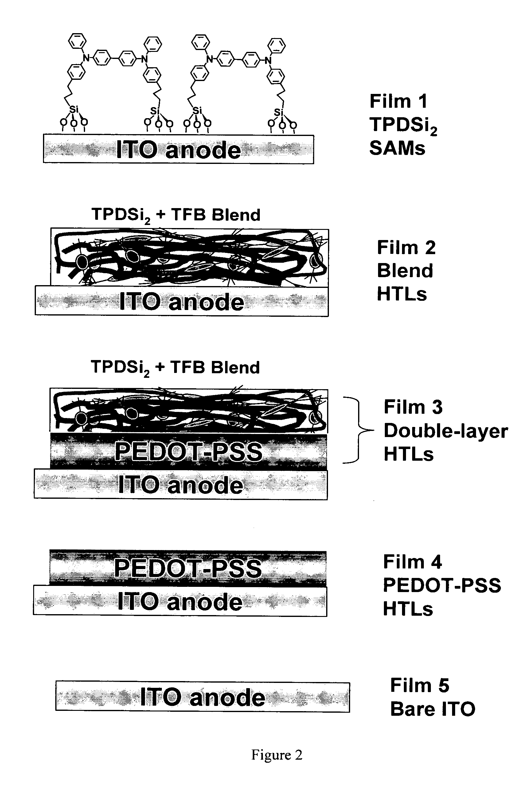
[0053] Fabrication procedure for TPDSi2 self-assembled monolayers (SAMs). Clean ITO substrates were first treated with an O2 plasma for 3 min and then transferred to a dry, clean Schlenk flask. Following strict Schlenk protocol, the Schlenk flask was further dried using a flame or a heatgun, followed by addition of a 1.0 mM dry toluene solution of TPDSi2 into the Schlenk flask by syringe. The ITO substrates were immersed in the TPDSi2 solution at ˜95° C. for 40 min, followed by rinsing and sonication with anhydrous toluene 3 times. The substrates were next immersed in a water / acetone mixture (1:100) with sonication for 5 min and then transferred to a 120° C. oven for 30 min. Silyl-derivatized TPD and TAA are prepared as described in the aforementioned applications, as well as in the literature. See, J. Cui, Q. Huang, J. G. C. Veinot, H. Yan, and T. J. Marks, Adv. Mater. 14, 565 (2002); and J. Cui, Q. Huang, Q. Wang, and T. J. Marks, Langmuir 17, 2051-2054. (2001).


PUM

PropertyMeasurementUnit
Transport propertiesaaaaaaaaaa
Bondaaaaaaaaaa

Abstract

Hole transport layer compositions comprising a silylated aryl amine and a polymeric component, to enhance performance of an associated electroluminescent device.

Description

[0001] This application claims priority benefit from application Ser. No. 60 / 528,325 filed Dec. 10, 2003, the entirety of which is incorporated herein by reference.[0002] The United States government has certain rights to this invention pursuant to Grant No. DMR-0076097 from the National Science Foundation to Northwestern University.BACKGROUND OF THE INVENTION [0003] Impressive scientific and technological progress has recently been achieved in the area of organic light-emitting diodes (OLEDs), motivated by potential applications in a large variety of display technologies. OLEDs are “dual-injection” devices in which holes and electrons are injected from opposite electrodes into an active molecular / macromolecular medium to produce, via exciton decay, light emission. OLED responses are usually evaluated with respect to the following characteristics: luminance—light intensity per unit area, turn-on voltage—voltage required for a device to reach luminance of ˜1 cd / m2, and current effici...

Claims


Application Information

Patent Timeline
IPC IPC(8): H01B1/12H01L51/00H01L51/50H05B33/12
CPCH01L51/0003H01L51/0037H01L51/0038H01L51/0039H01L51/0043H01L2251/308H01L51/0059H01L51/0075H01L51/0094H01L51/5048H01L51/0052Y10S428/917H10K71/12H10K85/115H10K85/1135H10K85/114H10K85/151H10K85/615H10K85/631H10K85/701H10K85/40H10K50/14H10K2102/103H01B1/12
Inventor MARKS, TOBIN J.YAN, HEHUANG, QINGLAN
Owner NORTHWESTERN UNIV
Why Eureka
Try Eureka