Molecular wire injection sensors

a technology of molecular wire and sensors, which is applied in the field of biosensors and chemical sensors, can solve the problems of inability to remove complex mixtures inside the permselective membrane, inability to remove complex mixtures, and almost all oxidation of ambient oxygen, and achieves fast response, high dynamic range, and high sensitivity

Inactive Publication Date: 2006-06-01
KEENSENSE
View PDF99 Cites 196 Cited by
  • Summary
  • Abstract
  • Description
  • Claims
  • Application Information

AI Technical Summary

Benefits of technology

[0045] Sensors of this invention provide analyte concentration readings, fast responses, high sensitivity, high dynamic range, and few erroneous readings. In a glucose sensor of this invention, glucose concentration is accurately read despite changes in partial pressure of O2, atmosphere, altitude, humidity, or sample application of blood. Specifically, the direct wired enzyme sensors of the present invention overcome the difficulty caused by molecular ox

Problems solved by technology

The inside permselective membrane is not always capable of removing the complicated mix of possible interferences from the analyte matrix.
Otherwise, ambient oxygen would oxidize nearly all of the reduced GOD and the desired signal would be very weak.
Unfortunately, mediators are commonly provided as mobile “reagents” which diffuse to the enzyme where they are oxidized or reduced (depending upon the reaction catalyzed by the enzyme).
Unfortunately, such mechanism is dependent upon the continuing presence of recycled mobile mediators.
As such compounds can leak from the electrode surfaces, there may be a gradual depletion in available mediator and a consequent reduction in sensor sensitivity.
Also, available sensors applying the above amperometric approach to the detection of glucose, cholesterol, lactate, H2O2, NAD(P)H, alcohol, and a variety of other compounds in whole blood samples, can have other serious complicating problems.
A related problem results from hydration of the reaction area prior to test.
Further, the partial pressure of molecular oxygen (O2) may complicate the interpretation of sensor data.
Calibration of GOD-based biosensors at different altitudes (i.e., different partial pressures of O2) may be a problem if electron transfer rates of selected synthetic chemical mediators are not orders of magnitude faster than the O2 side reaction.
Humidity (i.e., H2O) may be another potential problem if mass action of H2O and O2 present drives the enzyme catalyzed oxidation product of D-gluconolactone in reverse back to the reduced starting material, D-(+)-glucose.
Other problems associated with known amperometric sensors include, for example, (1) difficulty in fitting the Cottrell current curve (i.e., ampere-time graph), (2) sampling with enough frequency to accurately obtain the time integral of Cottrell current, (3) high applied potential at the electrode causing indiscriminate oxidation or reduction of interfering substances, and (4) complicated electronic circuits requiring potentiostat and galvinostat instrumentation.
First, due to the fact that the active site of redox enzymes is in general deeply buried within the protein shell, direct electron transfer between enzymes and electrode surfaces is rarely encountered.
Due to the necessity for the redox mediators to diffuse freely between the active sites of the enzymes and the electrode surface, these electrodes show a limited long-term stability as a c

Method used


Image

  • Molecular wire injection sensors
  • Molecular wire injection sensors
  • Molecular wire injection sensors

Examples


example a

Preparation of Polycrystalline Silicon p-n Junction Solar Cell

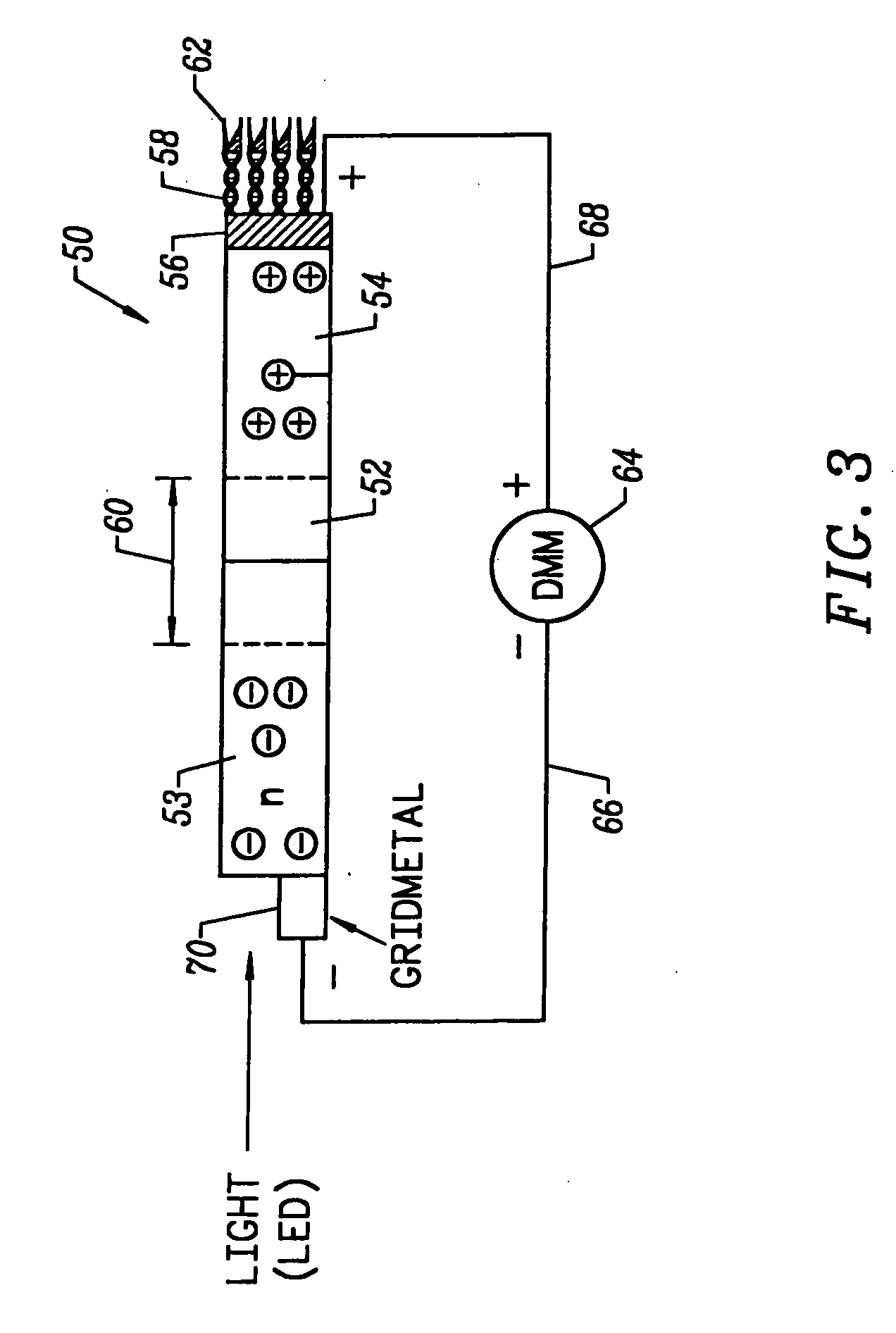
[0229] A commercial polycrystalline silicon p-n junction solar cell chip (a 0.1799 g and 1.75 cm2) from Edmund Scientific, Barrington, N.J. 08007-1380 (Stock Nos. 35,220 and 35,221) was exposed to 980 Lux light intensity from a F15T8 / CW Westinghouse bulb at 25° C. With the dark blue emitter surface facing the light source, the short circuit DC output of the dry solar cell substrate was measured by a digital multimeter (DMM) (Extech Instruments; Model No. 383273). Measured DC output was 121 mV and 98 uA. The solar cell chip was then washed with analytical reagent electronic-grade solvents: i) acetone; ii) methanol; iii) 18 Mohm H2O; and iv) methanol. It was allowed to dry in a dust-free environment. This prepared the semiconductor p-n type surfaces for electroplating.

example b

Electrodeposition of DNA onto a Polycrystalline Silicon p-n Junction Solar Cell

[0230] A DNA electroplating solution was prepared using 18 Mohm sterile water as the solvent. 0.1062 g of DNA (degraded free acid from Herring sperm) was added to 100 ml of water. The pH of the resulting solution was ˜2.00. The pH was adjusted to ˜7.00 with NaOH and HCl. No buffer was added to the electroplating solution. The final salt / electrolyte concentration was −2.

example c

Electrodeposition of Glucose Oxidase (GOD) onto a DNA-Coated Polycrystalline Silicon p-n Junction Solar Cell

[0231] A glucose oxidase (GOD) electroplating solution was prepared using 18 Mohm sterile water as the solvent. 0.0092 g of glucose oxidase (EC 1.1.3.4; ˜1,000 units) was added to 100 ml of water. The pH of the resulting solution was ˜6.00. No buffer or further adjustment of pH was necessary. 1.00 ml of methanol was added to the GOD electroplating solution and mixed thoroughly. Next, the DNA-coated polycrystalline silicon p-n junction solar cell from Example B was submerged in the GOD electroplating bath with dark blue emitter surface exposed to 1700 Lux light intensity from two F15T8 / CW Westinghouse bulbs at 25° C. for ˜8.10 hours. The solar cell chip was removed from the GOD bath and placed on a paper towel to dry. The dark blue emitter surface was exposed to the 1700 Lux light source during the drying process which took ˜12.00 hours at 25° C. in air. GOD electroplated on t...


PUM

PropertyMeasurementUnit
Electrical conductoraaaaaaaaaa
Affinityaaaaaaaaaa
aaaaaaaaaa

Abstract

Disclosed is a sensor for sensing the presence of an analyte component without relying on redox mediators. This sensor includes (a) a plurality of conductive polymer strands each having at least a first end and a second end and each aligned in a substantially common orientation; (b) a plurality of molecular recognition headgroups having an affinity for the analyte component and being attached to the first ends of the conductive polymer strands; and (c) an electrode substrate attached to the conductive polymer strands at the second ends. The electrode substrate is capable of reporting to an electronic circuit reception of mobile charge carriers (electrons or holes) from the conductive polymer strands. The electrode substrate may be a photovoltaic diode.

Description

CROSS-REFERENCE TO RELATED APPLICATIONS [0001] This application is a continuation-in-part, claiming priority under 35 U.S.C. § 120, from U.S. patent application Ser. No. 10 / 770,914, filed Feb. 2, 2004, naming inventor Randy E. Keen, and titled “MOLECULAR WIRE INJECTION SENSORS,” which is in turn a continuation of U.S. patent application Ser. No. 09 / 960,165, filed Sep. 20, 2001 naming inventor Randy E. Keen, which is now U.S. Pat. No. 6,699,667, issued Mar. 2, 2004, which is a continuation-in-part of U.S. patent application Ser. No. 09 / 365,109 filed on Jul. 30, 1999, which is now U.S. Pat. No. 6,326,215 issued on Dec. 4, 2001, which is a divisional of U.S. application Ser. No. 08 / 856,822, filed May 14, 1997, now U.S. Pat. No. 6,060,327, issued May 9, 2000. Each of these applications is incorporated herein by reference for all purposes.BACKGROUND OF THE INVENTION [0002] The present invention relates to biosensors and chemical sensors. More particularly, it relates to sensors having a ...

Claims


Application Information

Patent Timeline
IPC IPC(8): G01N33/53C12Q1/26C12M1/34
CPCB82Y10/00C12Q1/001C12Q1/006C12Q1/26G01N33/5438Y10S436/806
Inventor KEEN, RANDY E.
Owner KEENSENSE
Why Eureka
Try Eureka