Acene compounds having a single terminal fused thiophene as semiconductor materials for thin film transistors and methods of making the same

a technology of fused thiophene and acene compounds, which is applied in the field of acene compounds, can solve the problems of amorphous silicon still having its drawbacks, amorphous silicon still has its drawbacks, and limited application of amorphous silicon to low speed devices

Inactive Publication Date: 2006-10-05
EASTMAN KODAK CO
View PDF6 Cites 11 Cited by
  • Summary
  • Abstract
  • Description
  • Claims
  • Application Information

AI Technical Summary

Benefits of technology

[0015] (a) depositing, onto a substrate, a thin film of organic semiconductor material comprises a compound comprising a linear configuration of at least three fused benzene rings, which compound has, at one end only of the linear configuration, a terminal ring that is a fused substituted or unsubstituted thiophene, fused on its b side to an adjacent fused benzene ring, such that the thin film of organic semiconductor material exhibits a field effect electron mobility that is greater than 0.01 cm2 / Vs;

Problems solved by technology

Application of amorphous silicon is limited to low speed devices, however, since its maximum mobility (0.5-1.0 cm2 / Vsec) is about a thousand times smaller than that of crystalline silicon.
Although amorphous silicon is less expensive than highly crystalline silicon for use in TFTs, amorphous silicon still has its drawbacks.
The deposition of amorphous silicon, during the manufacture of transistors, requires relatively costly processes, such as plasma enhanced chemical vapor deposition and high temperatures (about 360° C.) to achieve the electrical characteristics sufficient for display applications.
Such high processing temperatures disallow the use of substrates, for deposition, made of certain plastics that might otherwise be desirable for use in applications such as flexible displays.
However, creating an ordered film from a disordered solution or from a vapor phase remains a challenge. C. Nuckolls et al (J. Am. Chem. Soc. 2004, 126, 15048-15050) recognized this dilemma and sought to functionalize one end of tetracene with methoxy or hydroxyl groups.
However, the placement of thiophenes at both ends of the acene inevitably leads to a cis-trans mixture.
In addition, the unique directing effect of a single ended asymmetric structure is lost with a symmetrical approach.

Method used


Image

  • Acene compounds having a single terminal fused thiophene as semiconductor materials for thin film transistors and methods of making the same
  • Acene compounds having a single terminal fused thiophene as semiconductor materials for thin film transistors and methods of making the same
  • Acene compounds having a single terminal fused thiophene as semiconductor materials for thin film transistors and methods of making the same

Examples


example i

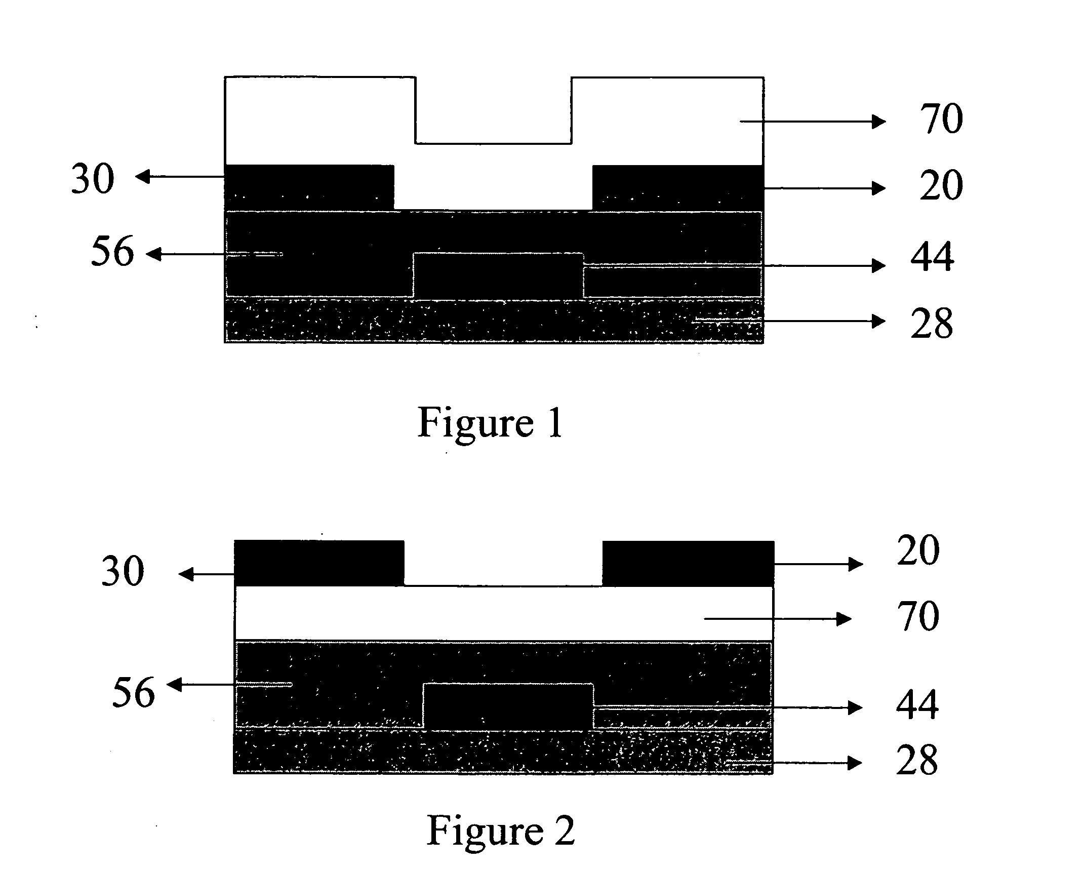
[0072] The active layer of Structure I was deposited via vacuum deposition in a thermal evaporator. A heavily doped silicon wafer with a thermally grown SiO2 layer with a thickness of 165 nm was used as the substrate. The wafer was cleaned for 10 minutes in a piranha solution, followed by a 6-minute exposure in an UV / ozone chamber. The cleaned surface was then treated with a thin layer of polystyrene by spin coating.

[0073] The purified semiconducting material was deposited by vacuum sublimation at a pressure of 5×10⁻⁷ Torr and a rate of 0.5 Angstroms per second to a thickness of 40 nm as measured by a quartz crystal. During deposition the substrate was held at a constant temperature of 60° C. The sample was exposed to air for a short time prior to subsequent deposition of Ag source and drain electrodes through a shadow mask to a thickness of 50 nm. The devices made had a 500 micron channel width, with channel lengths varying from 20-80 microns. The mobility was 5.38×10⁻³ cm2 / V-s, a...

example ii a and ii b

[0074] The active layer of Structure II was deposited via spin coating at 1200 rpm from a 0.2 wt % solution in chlorobenzene (A) or fluorobenzene (B). A heavily doped silicon wafer with a thermally grown SiO2 layer with a thickness of 215 nm was used as the substrate. The wafer was cleaned for 10 minutes in a piranha solution, followed by a 6-minute exposure in an UV / ozone chamber. The surface had no further treatments. Immediately following semiconductor deposition, Au source and drain electrodes were evaporated through a shadow mask to a thickness of 50 nm. The devices made had a 500 micron channel width, with channel lengths varying from 20-100 microns. Devices spun from chlorobenzene resulted in mobilities of 5.0×10⁻¹ cm2 / N-s, and the on / off ratio was 2.9×10⁵. Devices spun from fluorobenzene resulted in mobilities of 8.0×10⁻² cm2 V-s, and the on / off ratio was 2.10×10⁵.

example iii a and iii b

[0075] The active layer of Structure III was deposited via spin coating at 1200 rpm from a 0.2 wt % solution in isopropyl alcohol (A) or chlorobenzene (B). A heavily doped silicon wafer with a thermally grown SiO2 layer with a thickness of 215 nm was used as the substrate. The wafer was cleaned for 10 minutes in a piranha solution, followed by a 6-minute exposure in an UV / ozone chamber. The surface had no further treatments. Immediately following semiconductor deposition, Au source and drain electrodes were evaporated through a shadow mask to a thickness of 50 nm. The devices made had a 500 micron channel width, with channel lengths varying from 20-100 microns. Devices spun from isopropyl alcohol resulted in a maximum mobility of 1.08×10⁻⁴ cm2 / V-s, with an on / off ratio of 9.40×10². Devices spun from chlorobenzene resulted in a mobility of 6.0×10⁻⁶ cm2 / V-s, with an on / off ratio of 5.5×10².

C. Device Measurement and Analysis

[0076] Electrical characterization of the fabricated device...


PUM

PropertyMeasurementUnit
temperatureaaaaaaaaaa
gate voltageaaaaaaaaaa
diameteraaaaaaaaaa

Abstract

A thin film transistor comprises a layer of organic semiconductor material comprising a comprising, in a thin film transistor, a thin film of organic semiconductor material that comprises an acene compound having a linear configuration of at least three fused benzene rings, which compound has, at one end only of the linear configuration, a terminal ring that is a fused substituted or unsubstituted thiophene, fused to an adjacent fused benzene ring of the acene compound.

Description

FIELD OF THE INVENTION [0001] The present invention relates to the use of acene compounds containing a single terminal fused thiophene group as semiconductor materials in semiconductor films for thin film transistors. The invention relates to the use of these materials in thin film transistors for electronic devices and methods of making such transistors and devices. BACKGROUND OF THE INVENTION [0002] Thin film transistors (TFTs) are widely used as a switching element in electronics, for example, in active-matrix liquid-crystal displays, smart cards, and a variety of other electronic devices and components thereof. The thin film transistor (TFT) is an example of a field effect transistor (FET). The best-known example of an FET is the MOSFET (Metal-Oxide-Semiconductor-FET), today's conventional switching element for high-speed applications. Presently, most thin film devices are made using amorphous silicon as the semiconductor. Amorphous silicon is a less expensive alternative to cry...

Claims


Application Information

Patent Timeline
Patent Type & Authority Applications(United States)
IPC IPC(8): H01L29/08C07D333/50
CPCC07D333/50H01L51/0055H01L51/0074Y02E10/549H01L51/0541H01L51/0545H01L51/0094H10K85/623H10K85/6576H10K85/40H10K10/464H10K10/466
Inventor BAILEY, DAVID B.MAI, XUANSCUDERI, ANDREA C.LEVY, DAVID H.
Owner EASTMAN KODAK CO
Why Eureka
Try Eureka