

Electrocatalyst for ethanol oxidation and direct ethanol fuel cell using the same
- Summary
- Abstract
- Description
- Claims
- Application Information
AI Technical Summary
Benefits of technology
Problems solved by technology
Method used
Image

Examples
first embodiment
[0088] First, the structure of the fuel cell of the present invention will be explained in relation to the construction and operation of the present invention.
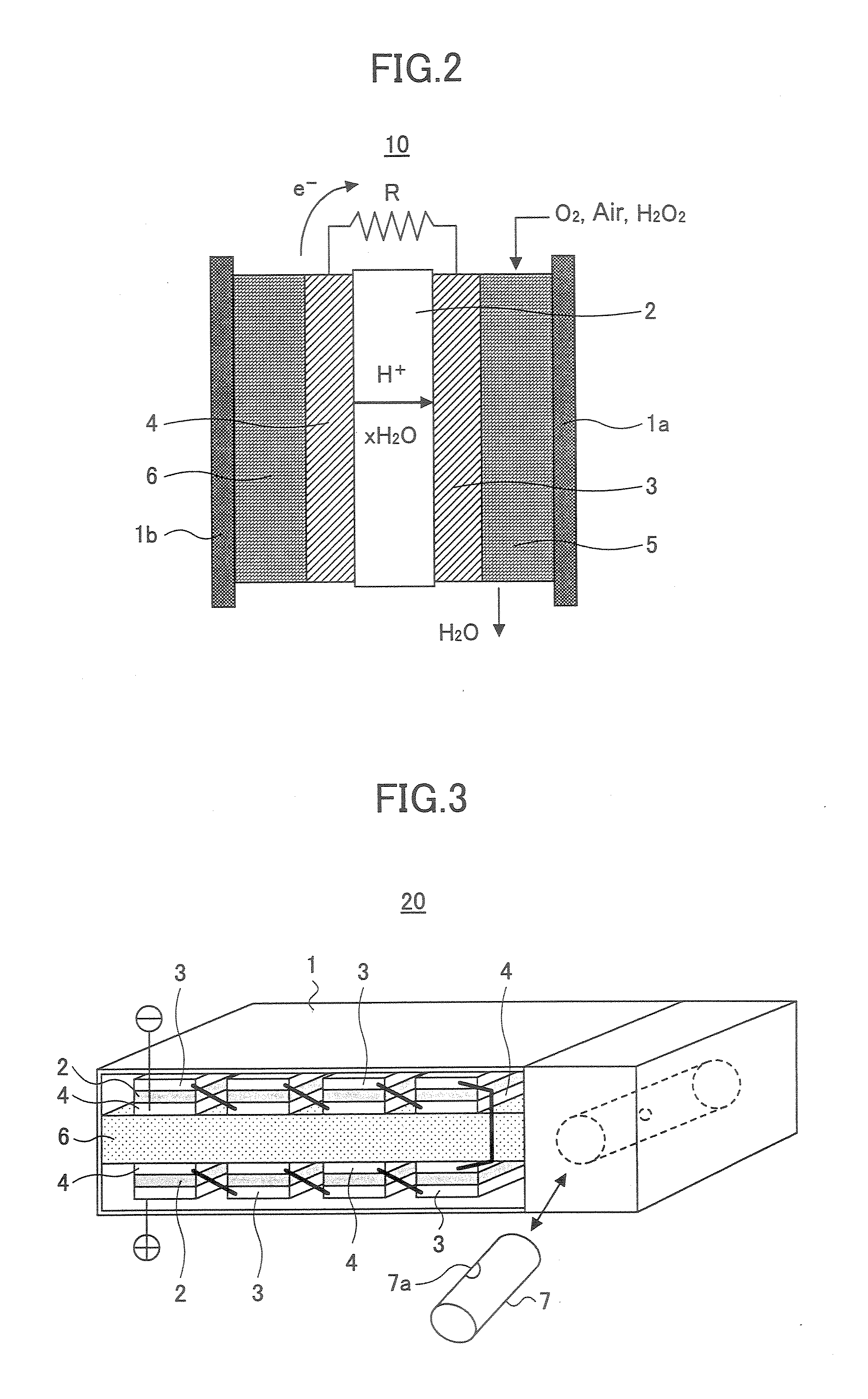
[0089]FIG. 2 is a schematic diagram of a single cell structure constituting a single cell element of a general fuel cell, wherein the cell structure of FIG. 2 is used also in the present invention. Thus, FIG. 2 shows the construction of a direct ethanol polymer electrolyte fuel cell (PEFC) 10 according to an embodiment of the present invention.
[0090] Referring to FIG. 2, the PEFC 10 of the present invention includes an ion exchange membrane 2, a cathode 3 that supports the ion exchange membrane 2 and an anode 4 in a housing represented by the numerals 1a and 1b, wherein there are further provided with an oxidizer channel 5 and a liquid fuel storage part 6 at the respective outer sides of the cathode 3 and the anode 4.
[0091] Any of anion conduction type and cation conduction type can be used for the ion exchange membrane 2, ...
second embodiment
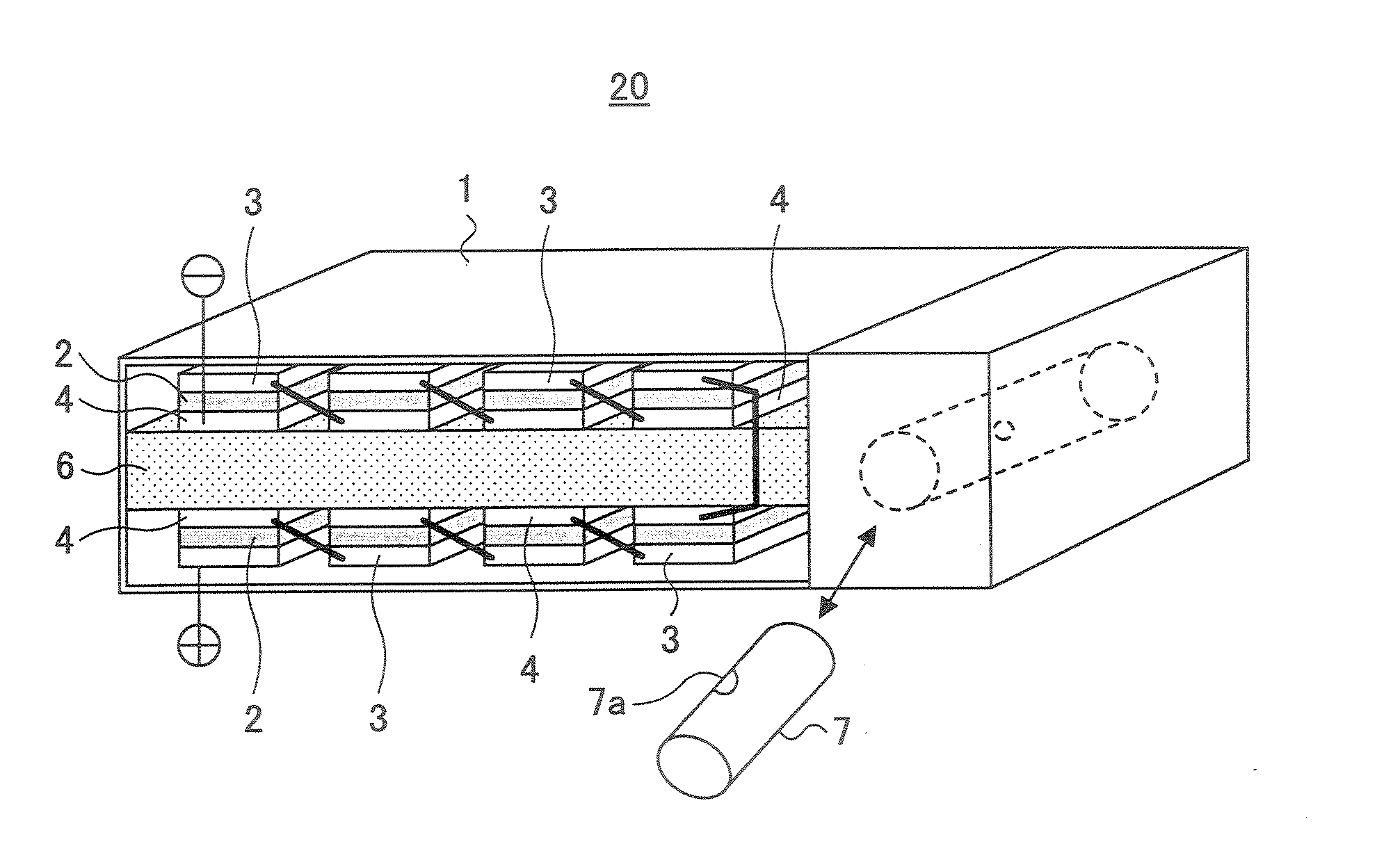
[0103]FIG. 3 is a schematic diagram showing the construction of a PEFC 20 according to a second embodiment of the present invention.
[0104] Referring to FIG. 3, it can be seen that the PEFC 20 of the present embodiment has a generally flat rectangular shape.
[0105] Within the PEFC 20, there is formed a fuel supply path 6 so as to divide the interior of the PEFC 20 to an upper part and a lower part, and there is further provided a storage part of the liquid fuel in the form of a cylindrical container 7.
[0106] It should be noted that the container 7 is provided detachably to the body of the PEFC 20 and the fuel stored in the container 7 is supplied to the fuel supply path 6 through a small hole 7a formed in the sidewall of the container 7. The hole 7a is closed by a seal (not shown) in the state before the container 7 is mounted inside the body of the fuel cell and the ethanol fuel is sealed in the container 7. It should be noted that the small hole 7a is formed in the position where...
example 10
[0128] Hereinafter, the result of characterization of the multicomponent alloy catalyst of the present invention will be shown for the composition and structure as Example 10. In the present embodiment, a multicomponent alloy formed by sputtering is presented as a typical example.
[0129]FIG. 5 shows the result of analysis of the crystal structure of the catalyst layer by XRD (X-ray diffraction) method.
[0130] Referring to FIG. 5, it can be seen that the catalyst layer of the Pt show a diffraction peak of fcc (face centered cubic) structure. Although not illustrated in FIG. 5, similar XRD analysis reveals that the catalyst layer of the Ru has an hcp (hexagonal closest packing) structure. Further, it was confirmed that the catalyst layer of the W has a ccp (cube closest packing) structure.
[0131] In the case of the Pt—Ru binary catalyst layer, the peak of Pt and Ru are basically observed although the peak position is shifted slightly from the characteristic peak of the simple metal. T...
PUM
| Property | Measurement | Unit |
|---|---|---|
| Percent by atom | aaaaa | aaaaa |
| Percent by atom | aaaaa | aaaaa |
| Percent by atom | aaaaa | aaaaa |
Abstract
Description
Claims
Application Information