Spongelike Structure and Powder, As Well As Process for Producing the Same

a sponge-like structure and powder technology, applied in the field of sponge-like structure or spherical powder, can solve the problems of reducing the bulkiness of the sponge-like structure, the limit of freely controlling the apparent density, and the difficulty of changing the filling density, etc., to achieve small apparent density, high porosity, and high porosity

Inactive Publication Date: 2009-03-05
TORAY IND INC
View PDF8 Cites 32 Cited by
  • Summary
  • Abstract
  • Description
  • Claims
  • Application Information

AI Technical Summary

Benefits of technology

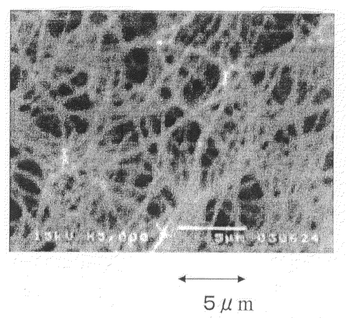
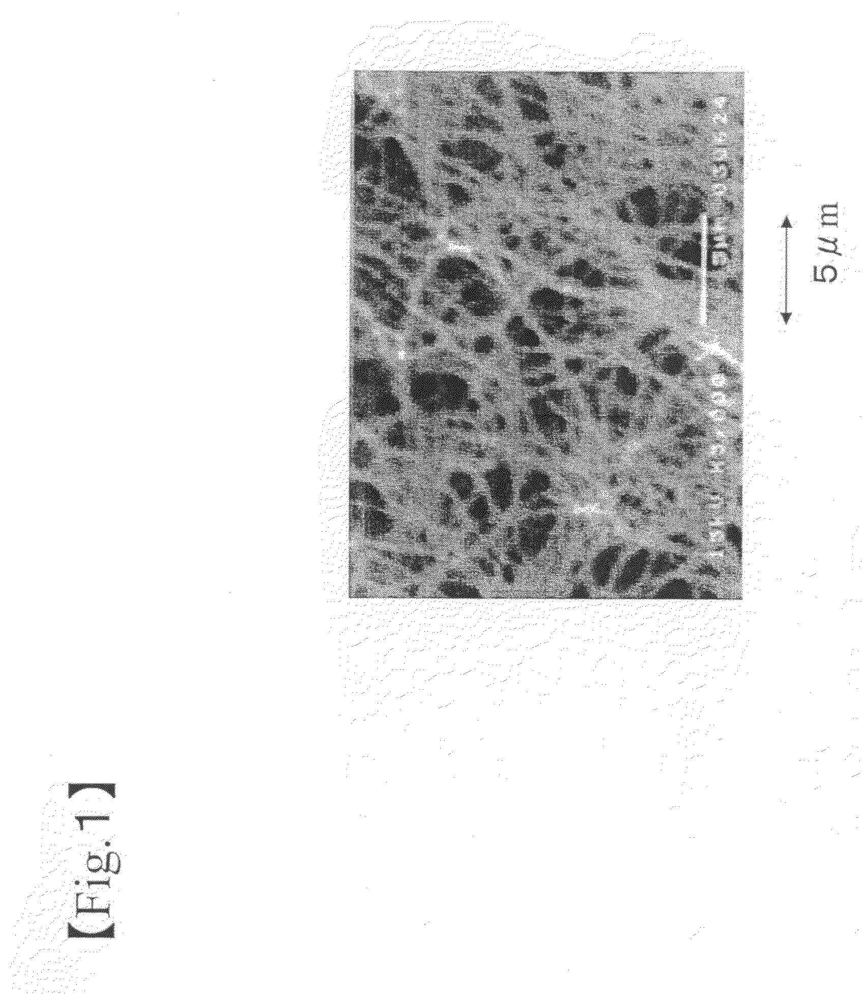
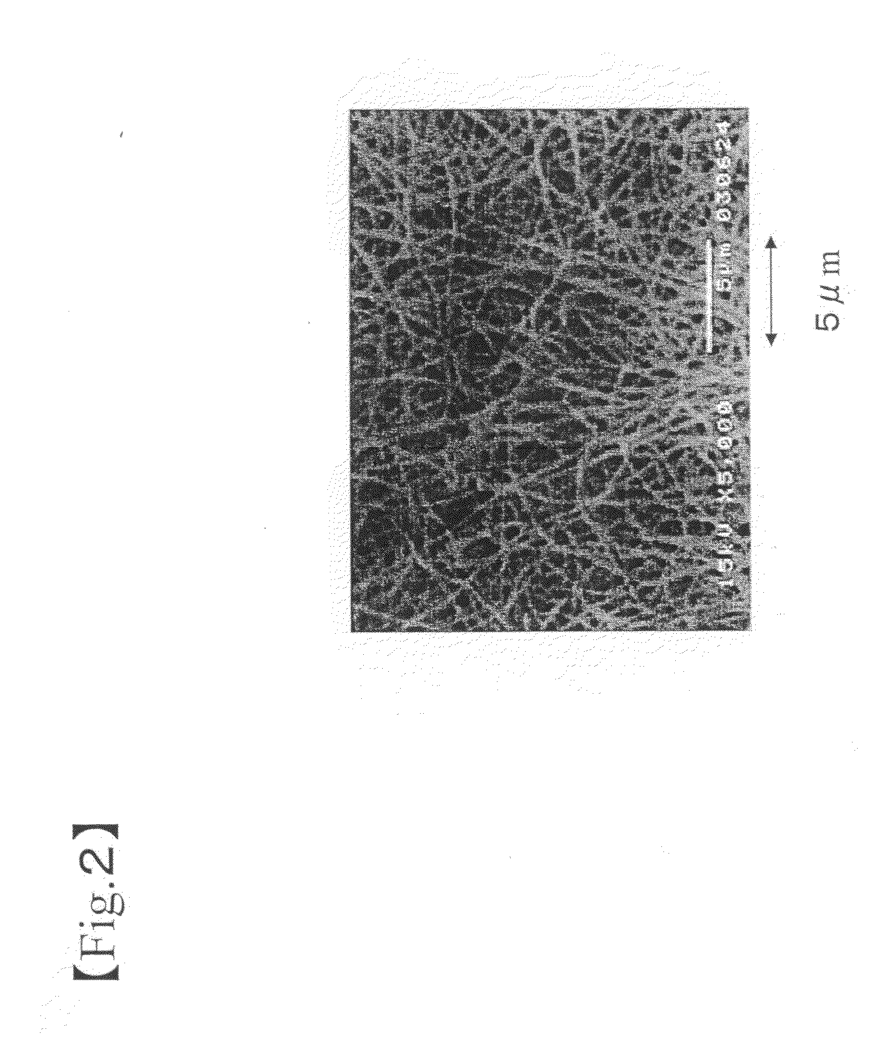
[0021]According to the present invention, a spongelike structure having a small apparent density and high porosity can be obtained. For this reason, the spongelike structure can be widely used in industrial material field and household wares field such as a light reflector used in a liquid crystal, an adsorbent, a cushioning material, and a water retention material in addition to a heat insulator, an acoustic material, and a cell scaffold material, utilizing such the property. In addition, since the spongelike structure has a micropore of a network structure, it can be utilized as various filters not only for household wares and industrial material but also for medicine. Further, the spongelike structure can be widely used in each field of esthetics, medical service, hygiene and the like.
[0022]When the spongelike structure of the present invention is used as a cell scaffold material, a cell scaffold material which can retain a cell and a culture medium in the interior of the structure and which has such a high porosity that a culture medium can be passed therethrough can be obtained. For this reason, a cell can be cultivated at a high density. Further, since the cell scaffold material of the present invention has a particularly high specific surface area, there is the effect that, by controlling a surface nature of the spongelike structure constituting a cell scaffold material by various treatments, it becomes possible to adsorb and carry a functional substance having a function on a cell, a representative which is a protein such as cytokine, on a fiber surface at a high density, and effective cultivating can be performed. At the same time, since the spongelike structure is similar to an extracellular matrix which is a fibrous material at a nano-level, a representative of which is collagen, surrounding a cell in bone marrow, basement membrane and amnion in which many functional cells such as stem cells, hematopoietic cells and mesenchymal cells are grown in a living body, these functional cells which have been previously difficult to be cultivated can be cultivated while the function is retained or promoted. For this reason, it becomes possible to apply the spongelike structure to the field of medical service, diagnosis, research and analysis related to cell culture or tissue regeneration using these cells, particularly the medical field such as regenerative medicine and cell therapy.
[0023]Further, according to the present invention, a powder of a granular structure having a constituent fiber of a small diameter and a small apparent can be obtained. For this reason, the powder utilizing such the property can be widely used not only as a filler for a resin, a paint and a cosmetic but also as an adsorbent or a water retention agent and, further in each field of medical service, and hygiene.
[0024]In addition, according to each process of the present invention, in all cases, since an apparent density can be easily designed and changed depending on the object and utility, various spongelike structures and powders can be obtained.

Problems solved by technology

However, although such the structure has a low apparent density, it is not easy to change a filling density of a fiber in a molding box since fibers are thermally adhered in the state where they are filled into a molding box in order to perform molding, and there is a limit for freely controlling an apparent density.
Further, in applications utilizing a specific surface area of a fiber, a smaller number mean diameter of a fiber is required, and as there is the description to the effect that, when a fineness of a single filament is less than 0.5 denier (less than 7 μm in terms of PET specific gravity), bulkiness of the spongelike structure is reduced, in a paragraph in the patent Publication, it is difficult to reduce an apparent density in the spongelike structure having a smaller fiber diameter.
However, there are a problem that a biomaterial consisting mainly of a protein can not stand severe treatment, a representative of which is sterile treatment such as autoclave and γ-ray, which is frequently performed in a process for manufacturing a medical material, a problem on stability for long term storage until use, and a problem on a dynamical strength and shape stability.
In addition, since a biomaterial such as collagen is generally extracted from an animal such as a cow and a pig, there is a risk that a known or unknown infectious material from these animals, a representative of which is a virus and a prion, is mixed in, and this was a problem upon use as a scaffold material for cultivating a cell in vivo and in vitro, particularly, upon use in medical utility.
However, these previous three-dimensional cultivating scaffolds using a synthetic polymer as a material have not an actual shape of a fibrous material called extracellular matrix surrounding a cell in vivo, a representative of which is collagen, particularly a structure mimicking a structure consisting of a fiber at a nano-level.
For this reason, they can not be said to mimic the in vivo environment truly, are inferior in affinity for a cell, and influence due to inability to express the cell function as in vivo on the previous scaffold is concerned.
However, the structure obtained by such the electrospinning has a defect for use in a scaffold material for cultivating a cell, such as weakness of a fiber strength, ununiformity and scatter of a fiber diameter, and use of an organic solvent upon manufacturing.
In addition, since a special process called electrospinning as described above is used, a shape of the resulting structure is limited to a so-called paper-like non-woven fabric structure.
That is, it is substantially impossible to cultivate a cell at a high density, and it is also impossible to regenerate and reconstruct an organ or a tissue having a thickness in vitro.
Further, a non-woven fabric structure also has a defect that a three-dimensional environment in a living body such as bone marrow in which a cell is grown can not be truly reproduced from a view point of a shape.
For this reason, there is a problem that, when added as filler for a resin, a paint and a cosmetic, dispersity is inferior due to fibers aggregation and its settlement, storage stability is reduced, and when these are coated, uniform coating is difficult.

Method used


Image

  • Spongelike Structure and Powder, As Well As Process for Producing the Same
  • Spongelike Structure and Powder, As Well As Process for Producing the Same
  • Spongelike Structure and Powder, As Well As Process for Producing the Same

Examples


production example 1

of Dispersion

[0180]N6 (20 weight %) having a melt viscosity of 57 Pa·s (240° C., shearing rate 2432 sec−1) and a melting point of 220° C., and poly-L lactic acid (optical purity 99.5% or higher) (80 weight %) having a weight average molecular weight of 120 thousands, a melt viscosity of 30 Pa·s (240° C., shearing rate 2432 sec−1) and a melting point of 170° C. were melted and kneaded with a double-screw extruder at 220° C. to obtain a polymer alloy chip. A melt viscosity of N6 at 262° C. and a shearing rate of 121.6 sec−1 was 53 Pa·s. In addition, a melt viscosity of this poly-L lactic acid at 215° C. and a shearing rate of 1216 sec−1 was 86 Pa·s. In addition, the kneading condition thereupon was as follows.

Polymer supply: N6 and poly-L lactic acid were separately weighed, and supplied to a kneader separately.

Screw type: Same directional complete fitting type W-start thread

Screw: diameter 37 mm, effective length 1670 mm,

L / D: 45.1

[0181]A kneading part length is positioned on a discha...

production example 2

of Dispersion

[0187]According to the same manner as that of Production Example 1 of dispersion except that N6 of Production Example 1 of dispersion was changed to N6 (45 weight %) having a melt viscosity of 212 Pa·s (262° C. shearing rate 121.6 sec−1), and a melting point of 220° C., melt kneading was performed to obtain a polymer alloy chip. Then, this was melt-spun and drawing-heat-treated as in Production Example 1 of dispersion to obtain a polymer alloy fiber. The resulting alloy fiber exhibited excellent properties of 67 dtex, 36 filaments, a strength of 3.6 cN / dtex, elongation of 40%, and U %=0.7%. In addition, when a cross section of the resulting polymer alloy fiber was observed with TEM, an island in sea structure in which poly-L-lactic acid is a sea and N6 is an island was shown as in Production Example 1 of dispersion, a number mean diameter of the island N6 was 110 nm, and a polymer alloy fiber in which N6 is uniformly dispersed was obtained.

[0188]According to the same ma...

production example 3

of Dispersion

[0190]According to the same manner as that of Production Example 2 of dispersion except that a content of a N6 nano-fiber was adjusted to 0.1% by weight by changing a fiber amount after refining without changing amounts of water and a dispersant to be placed into an Oster blender (manufactured by Oster), a dispersion 3 of a N6 nano-fiber was obtained.


PUM

PropertyMeasurementUnit
number mean diameteraaaaaaaaaa
apparent densityaaaaaaaaaa

Abstract

An object of the present invention is to provide a spongelike structure or a powder having fibers three-dimensionally arranged therein with high dispersibility, whose apparent density can be designed depending on the purpose or utility, as well as a process producing them. A fiber dispersion in which fibers having a number mean diameter in a predetermined range are dispersed in a dispersion medium, and this fiber dispersion is dried to remove the dispersion medium, thereby, a spongelike structure and a powder are produced.

Description

TECHNICAL FIELD[0001]The present invention relates to a spongelike structure or a spherical powder in which a fiber is dispersed and arranged three-dimensionally, and a process for producing the same.BACKGROUND ART[0002]Previously, as a spongelike structure, a variety of moldings are known. For example, there is a molding obtained by mixing a polymer with a blowing agent, placing this into a molding box, and heating to expand this. Specifically, there are expanded foams consisting of urethane, polyolefin or melamine resin. In addition, there are moldings obtained by blending a dissolution material in a polymer, and dissolving out this to form micro pores.[0003]Since the structure obtained by the aforementioned procedure has high porosity, it is widely utilized as a heat insulator, an acoustic material, an adsorbent, a cushioning material or a filter.[0004]Further, in addition to the expanded foams, a spongelike structure obtained by arranging fibers three-dimensionally is also known...

Claims


Application Information

Patent Timeline
Patent Type & Authority Applications(United States)
IPC IPC(8): A61K8/02C12M3/00B05D3/02D04H1/70D04H1/42
CPCA61K8/02A61K8/0208A61Q1/12Y10T428/298A61Q19/08D21H13/10A61Q19/00A61K8/72D04H1/42D04H1/732C08J9/28C08J9/36C08J2323/12C08J2367/03C08J2377/02C08J2381/04
Inventor NARUSE, YOSHIHIROKONDO, SATOSHINONAKA, SHUICHIMIWA, KEISHIMURAKAMI, KAKUJI
Owner TORAY IND INC
Why Eureka
Try Eureka