Patterning process

a pattern and process technology, applied in the field of pattern formation process, can solve the problems of low resist resistance etching resistance, high cost of scanner, and obviation of bubble generation risk, so as to achieve high contrast, high contrast, and difficult pattern formation

Active Publication Date: 2009-03-26
SHIN ETSU CHEM IND CO LTD
View PDF10 Cites 42 Cited by
  • Summary
  • Abstract
  • Description
  • Claims
  • Application Information

AI Technical Summary

Benefits of technology

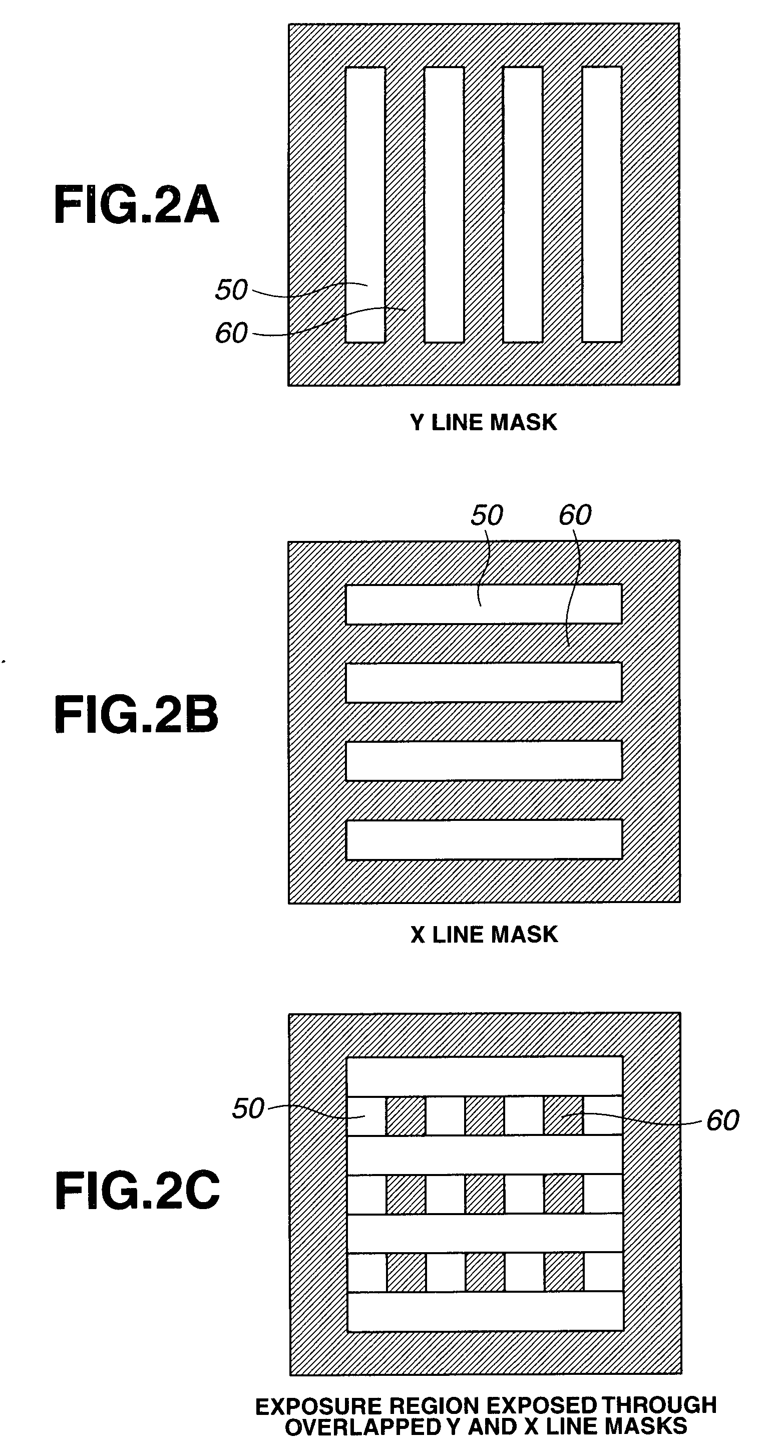
[0062]The gradient of a curve at the mask edge represents an image contrast. A greater gradient is more advantageous to pattern formation. The sequence of high to low contrast is in the order of line, dot and hole patterns. Since the contrast of the hole pattern is extremely low, pattern formation is difficult even with a very high contrast resist film. The dot pattern provides a somewhat higher contrast than the hole pattern. The line pattern exhibits a high contrast under the dipole illumination, which is a more intense oblique incidence illumination, plus intense s-polarized illumination, achieving a higher maximum resolution than the dot and hole patterns which are two-dimensional patterns incompatible with intense modified illumination. This indicates that formation of a fine hole pattern is one of the challenges of the lithography technology. It is also indicated that more advanced miniaturization is achievable if a hole pattern is formed by reversal of a dot pattern. A dot pattern can be formed by the double dipole method involving exposure of a X-direction line pattern, exposure of a Y-direction line pattern, and development. The dot pattern formed by this method has finer features than the ordinary methods using a dot patterned mask.
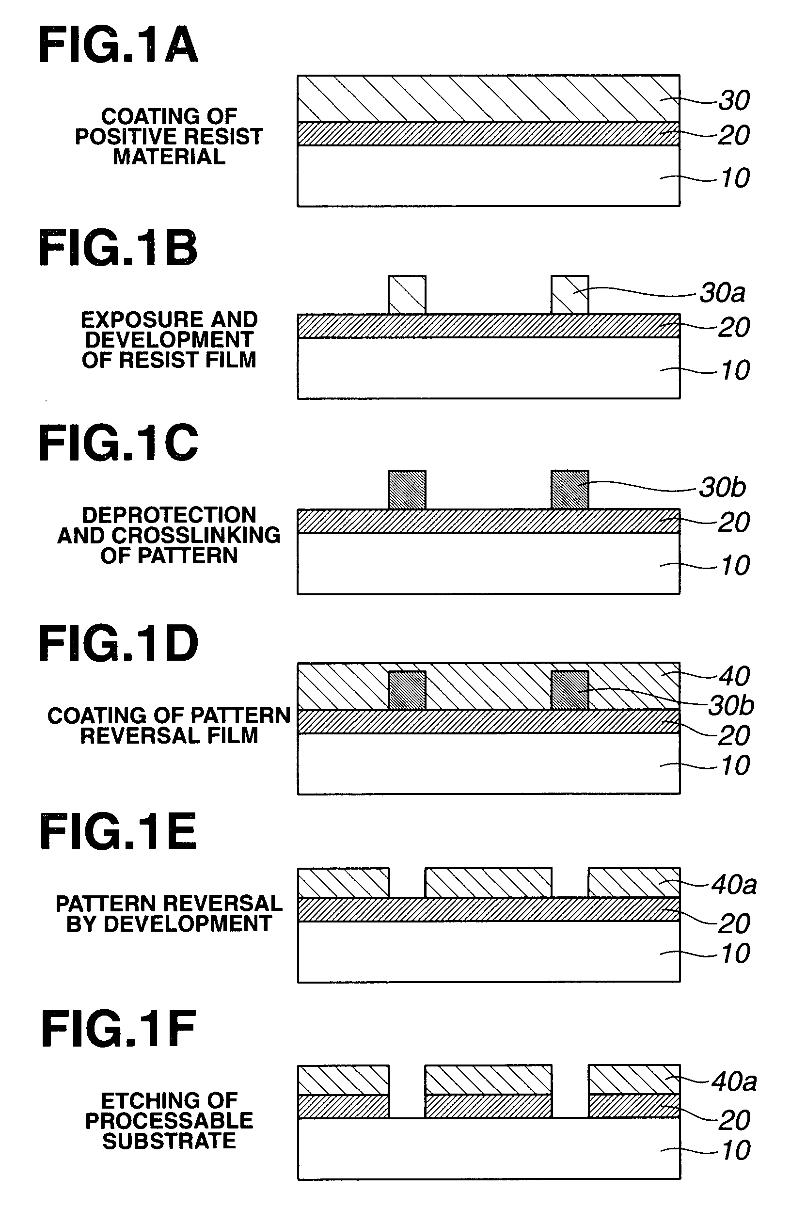
[0063]According to the invention, when a reversal film is formed on a positive pattern by coating a reversal film-forming composition using a solvent containing a hydroxy-bearing solvent or a highly polar solvent such as an ester or ketone, the reversal film-forming composition can be buried in spaces in the positive pattern without any damage to the positive pattern; and the positive pattern resulting from a positive resist composition can be removed by wet etching. Thus, positive / negative reversal at a high accuracy can be performed by a simple procedure. Moreover, an organic material which fails to establish a selectivity between it and the resist pattern upon oxygen dry etching which is a prior art resist pattern removal method can be used in the reversal film. Moreover, a material which is difficult to dissolve unless a hydroxy-bearing solvent or a highly polar solvent such as an ester or ketone is used, like a resin material which is improved in adhesion by incorporating polar groups such as hydroxy groups, especially phenolic hydroxy groups or lactone structures, can also be used in the reversal film. In this case, to process a silicon oxide film by a prior art method, the reversed pattern must be transferred to an organic film before the silicon oxide film can be processed. With the inventive process, the reversed pattern allows for direct processing.
[0064]Also, when a reversal film having an appropriate alkali dissolution rate is used as the reversal film, the step of removing the portion of the reversal film overlying the positive pattern and the step of wet etching the positive pattern may be performed simultaneously, achieving a significantly simplified process.
[0065]Image reversal from a positive pattern to a negative pattern by this method ensures that using a first fine line pattern, a fine space pattern of the same size can be reversal-formed. In the case of a trench pattern, a line pattern having a capability to form a finer feature size is formed through exposure, and this is converted into a trench pattern by the image reversal technology described above, whereby an ultra-fine trench pattern can be formed. By reversal of a dot pattern, a hole pattern can also be formed. Moreover, once a line pattern is formed as a first pattern, a second line pattern extending perpendicular thereto is exposed and developed to form a dot pattern, and a film having an appropriate alkaline dissolution rate is coated and developed for image reversal to form a hole pattern. In this way, a hole pattern which is finer than the prior art hole pattern can be formed.

Problems solved by technology

However, for the reasons that the projection lens uses a large amount of expensive CaF2 single crystal, the scanner thus becomes expensive, hard pellicles are introduced due to the extremely low durability of soft pellicles, the optical system must be accordingly altered, and the etch resistance of resist is low; the postponement of F2 lithography and the early introduction of ArF immersion lithography were advocated (see Proc.
It was found that the risk of bubble generation is obviated by thorough deaeration of water and the risk of bubble generation from the resist film upon light exposure is substantially nil.
In optical systems based on traditional refractive index materials, this leads to giant lenses, which would deform by their own weight.
In the case of alkane compounds, bridged cyclic compounds are preferred to linear ones in order to increase the refractive index, but the cyclic compounds undesirably have too high a viscosity to follow high-speed scanning on the exposure tool stage.
While the former process requires two applications of hard mask, the latter process uses only one layer of hard mask, but requires to form a trench pattern which is difficult to resolve as compared with the line pattern.
These have the drawbacks that the proximity bias is degraded and the process is further complicated, leading to reduced throughputs.
Both the former and latter processes require two etchings for substrate processing, leaving the issues of a reduced throughput and deformation and misregistration of the pattern by two etchings.
However, these methods using negative resist materials with low resolution entail degradation of resolution.
However, the optical energy of second exposure offsets the optical energy of first exposure so that the contrast becomes zero, leading to a failure of pattern formation.
The critical issue associated with double patterning is an overlay accuracy between first and second patterns.
The negative resist suffers from the problem that the resist itself has a low resolution.
The thermal flow and RELACS methods suffer from a likelihood of variation during dimensional shrinkage by heat.
As compared with the line pattern, the hole pattern is difficult to reduce the feature size.
However, there is a problem that control accuracy becomes lower as the pattern size after development and the size after shrinkage are greater and the quantity of shrinkage is greater.
Although a hole pattern can be formed at a wide margin by combining X and Y lines and using dipole illumination featuring a high contrast, it is difficult to etch vertically staged line patterns at a high dimensional accuracy.

Method used


Image

  • Patterning process
  • Patterning process
  • Patterning process

Examples


example

[0414]Examples of the invention are given below by way of illustration and not by way of limitation. The abbreviations used herein are GPC for gel permeation chromatography, Mw for weight average molecular weight, Mn for number average molecular weight, Mw / Mn for molecular weight distribution or dispersity, NMR for nuclear magnetic resonance, PAG for photoacid generator, and TAG for thermal acid generator. For all polymers, Mw and Mn are determined by GPC versus polystyrene standards.

synthesis examples

[0415]Polymers for use in reversal film-forming compositions were prepared by combining various monomers, effecting copolymerization reaction in tetrahydrofuran medium, crystallization in methanol, repeatedly washing with hexane, isolation, and drying. The resulting polymers (Polymers 1 to 13 and Comparative Polymers 1 to 2) had the composition shown below. Notably, a phenol group on a monomer was substituted by an acetoxy group, which was converted back to a phenol group by alkaline hydrolysis after polymerization. The composition of each polymer was analyzed by 1H-NMR, and the Mw and Mw / Mn determined by GPC.

[0416]Polymer 11: a novolac resin of m-tert-butylphenol and 1-naphthol in a molar ratio of 6:4, with Mw 8,600 and Mw / Mn 4.8[0417]Polymer 12: a novolac resin of 4,4′-(9H-fluoren-9-ylidene)-bisphenol, with Mw 7,900 and Mw / Mn 5.1[0418]Polymer 13: a novolac resin of (9H-fluorene-9-ylidene)-bisnaphthol, with Mw 1,600 and Mw / Mn 3.8

[0419]Reversal film-forming compositions were prepare...


PUM


Abstract

A pattern is formed through positive/negative reversal by coating a chemically amplified positive resist composition comprising an acid labile group-bearing resin, a photoacid generator, and an organic solvent onto a substrate, prebaking the resist composition, exposing the resist film to high-energy radiation, post-exposure heating, and developing the exposed resist film with an alkaline developer to form a positive pattern; irradiating or heating the positive pattern to facilitate elimination of acid labile groups and crosslinking for improving alkali solubility and imparting solvent resistance; coating a reversal film-forming composition thereon to form a reversal film; and applying an alkaline wet etchant thereto for dissolving away the positive pattern.

Description

CROSS-REFERENCE TO RELATED APPLICATION[0001]This non-provisional application claims priority under 35 U.S.C. §119(a) on Patent Application Nos. 2007-247114 and 2008-027132 filed in Japan on Sep. 25, 2007 and Feb. 7, 2008, respectively, the entire contents of which are hereby incorporated by reference.TECHNICAL FIELD[0002]This invention relates to a process for forming a pattern by way of positive / negative reversal involving the steps of forming a positive pattern through exposure and development, acid-generating and heating treatment for converting the positive pattern to be alkali soluble, coating thereon a reversal film which is slightly alkali soluble, and effecting alkaline development to dissolve away a surface portion of the reversal film and the positive pattern to form a negative pattern.BACKGROUND ART[0003]In the recent drive for higher integration and operating speeds in LSI devices, the pattern rule is made drastically finer. The photolithography which is currently on wid...

Claims


Application Information

Patent Timeline
Patent Type & Authority Applications(United States)
IPC IPC(8): G03F7/20
CPCG03F7/0046G03F7/0397G03F7/11G03F7/2024H05K2203/0582G03F7/40H01L21/0273H01L21/0337H05K3/061G03F7/2041
Inventor HATAKEYAMA, JUNYOSHIHARA, TAKAOISHIHARA, TOSHINOBU
Owner SHIN ETSU CHEM IND CO LTD
Why Eureka
Try Eureka