Copper alloy and liquid-crystal display device
- Summary
- Abstract
- Description
- Claims
- Application Information
AI Technical Summary
Benefits of technology
Problems solved by technology
Method used
Image
Examples
first embodiment
[0078]The above embodiment is explained in further detail below.
[0079]Using a Cu—Mn alloy of Cu having a purity of 99.9999% and Mn having a purity 99.98% as sputtering target materials, a Cu-7 at. % Mn alloy thin film was formed on an Si substrate having SiO2 on its surface. The resultant alloy thin film was subjected to heat treatment in an Ar gas atmosphere (oxygen content: 100 ppm) at 400° C. for 30 minutes. Element concentration distribution in the thickness direction of a specimen from the surface was then determined using secondary ion mass spectrometry (SIMS).
[0080]FIG. 5 shows results of the concentration distribution determined by the SIMS.
A specimen was sputtered by an ion beam in the direction from the surface of the thin film to SiO2 and the mass of secondary ions being sputtered from the specimen was continuously measured to determine the concentration distribution inside the specimen. It has been found that MnOx is present on the surface. The presence of Cu, Mn, Si, an...
second embodiment
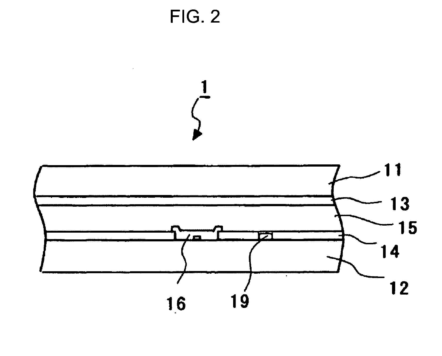
[0083]In a channel etched amorphous silicon (a-Si) TFT liquid crystal display device, the gate wiring shown in FIG. 2 is formed as follows. A Cu-2 at. % Mn alloy thin film is first formed on a cleansed glass substrate using a Cu-2 at. % Mn alloy of Cu having a purity of 99.9999% and Mn having a purity of 99.98% as a target material. A wiring pattern for gate line is formed on the resultant alloy thin film by a photoresist process and a dry etching process. The pattern is then subjected to heat treatment in an Ar gas atmosphere (oxygen content: 100 ppm) at 400° C. for 30 minutes. Stable oxide layers are formed at the interface between the Cu—Mn alloy and the glass substrate and on the surface of the Cu—Mn alloy.
third embodiment
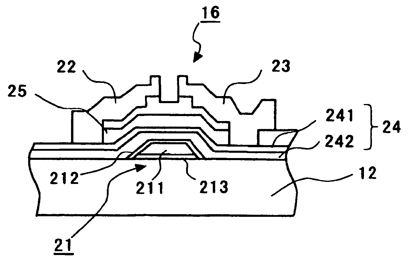
[0084]A planar polysilicon (p-Si) TFT liquid crystal display device is produced as follows. The p-Si film is first deposited on a cleansed glass substrate by a plasma enhanced chemical vapor deposition (PECVD) process, and then thoroughly subjected to laser annealing to form polycrystalline Si (p-Si). The p-Si film is patterned and then an SiO2 gate insulator film is formed by a CVD process. A film of a Cu-2 at. % Mn alloy is then formed by a sputtering process and etched to form a gate electrode. Next, the resultant substrate is subjected to heat treatment in a vacuum at 400° C. for 30 minutes. The substrate is subsequently doped with an impurity by an ion doping process, and a source and a drain are formed in a self-alignment manner, forming an interlayer dielectric film. The resultant substrate is then subjected to heat treatment at 400° C. for 30 minutes. FIG. 8 is a schematic diagram of thus formed planar polysilicon (p-Si) TFT through the above steps. In FIG. 8, an oxide compr...
PUM
| Property | Measurement | Unit |
|---|---|---|
| Thickness | aaaaa | aaaaa |
Abstract
Description
Claims
Application Information
 - R&D
- Intellectual Property
- Life Sciences
- Materials
- Tech Scout
- Unparalleled Data Quality
- Higher Quality Content
- 60% Fewer Hallucinations
Browse by: Latest US Patents, China's latest patents, Technical Efficacy Thesaurus, Application Domain, Technology Topic, Popular Technical Reports.
© 2025 PatSnap. All rights reserved.Legal|Privacy policy|Modern Slavery Act Transparency Statement|Sitemap|About US| Contact US: help@patsnap.com


