Manufacture of thin solar cells based on ink printing technology

a solar cell and ink printing technology, applied in the field of semiconductive ink compositions, can solve the problems of indium loss, cis module production is still too expensive to compete with polycrystalline si based solar modules, and the pve process is difficult to large-scale commercial-scale pv production, etc., to achieve high-performance solar cells, increase the open-circuit voltage of solar cells, and effectively absorb shorter wavelength sunlight

Active Publication Date: 2011-03-17
GUANMAT OPTOELECTRONIC MATERIALS (JIANGXI) INC
View PDF4 Cites 39 Cited by
  • Summary
  • Abstract
  • Description
  • Claims
  • Application Information

AI Technical Summary

Benefits of technology

[0015]For controlling the composition and therefore the solar cell's performance, a chalcogen element can optionally be added. The chalcogen element is sulfur, selenium or tellurium. The benefit of the addition of chalcogen in the ink is to compensate the loss of chalcogen of the CIGS nanoink coated film during drying or during annealing process. Not only for the purpose of perfection of the crystalline grain size of the semiconductor, can the chalcogen also alter the band gap of the final film. For instance, in a CuInSe2 film formed by printing of an ink with the ingredient of CuInSe2, a small amount of x sulfur in the liquid ink formulation can lead to the formation of CuInSe2-xSx upon annealing of the printed film under argon atmosphere. Thus formed sulfurized CuInSe2-xSx absorber can increase the open circuit voltage of the solar cell. The amount of addition of the chalcogen element is within the range of x=0-1.
[0016]It is within the scope of this disclosure that an optional thickening polymer is added into the semiconductive ink. The polymer thickening agent can stabilize the nanoparticle ink, and the polymer thickening agent is a thermal decomposable polymer (TDP) that will subject a complete removal upon heating not higher than 550° C. Examples of the thickening polymer can be preferably selected from poly(acrylate amide), poly(acrylate acid), poly(vinyl acetate).
[0017]The present invention also includes a method of fabrication single junction solar cells and advanced multi junction tandem solar cells with the use of the present disclosed ink. Such single junction solar cell will include a first electrode surface. The semiconductor ink is printed onto the first electrode surface to directly form p-type semiconductor thin film with large crystal grains suitable for high performance solar cell. After forming a p-n heterojunction with an n-type semiconductor, a second electrode is deposited to form the single p-n heterojunction solar cell. In a multi-junction monolithic solar cell, a p-type semiconductive thin film CuInxGa1-xSeyS2-y having a bandgap of about 1.0-1.2 eV is printed on a first electrode, and then form the bottom solar cell upon the deposition of a n-type semiconductor, and a transparent conducting oxide (TCO). Another p-type semiconductor thin film CuInxGa1-xSeyS2-y having a bandgap of about 1.6-2.4 eV is printed on to TCO of the bottom solar cell. After forming the upper p-n heterojunction with an n-type semiconductor, another second electrode is deposited to form the two junction tandem solar cell. In this monolithic two junction tandem solar cell, the absorber layer in the top cell has a higher band gap (1.6-2.4 eV), it can hence effectively absorb shorter wavelength sunlight, such as from 350 nm to 600 nm; and the absorber layer in the bottom cell has a lower bandgap (1.0 eV), it can hence effectively absorb longer wavelength sunlight, such as from 500 nm to 1150 nm.

Problems solved by technology

However, PVE process is difficult for large area commercial scale PV production due to its point-evaporation nature, and due to the difficulty for uniform composition control.
To date, the CIS modules produced are still too expensive to compete with polycrystalline Si based solar modules.
Due to the non-uniformity of composition caused by the large metal particle size (up to 2 μm), and the high sintering temperature, which causes indium loss and deforms the soda-lime glass substrate, PV performance was reported to be low, with efficiencies of only about 1%.
However, the CIGS nanoparticles are largely amorphous and the formed film is not desirable for high performance photovoltaic cell.
Besides, the large quantity of sodium iodide byproduct in the film may interfere the formation of crystalline particles.
Although precise control of the IB / IIIA elemental ratio is readily achieved by this method, the extra reduction and “selenization” process of the oxides are both complicated and costy, which limits the benefit of this non-vacuum process over co-evaporation process.
Besides, the difficulty to remove completely the trace oxide of gallium and indium also limits the performance of thus formed solar cells.
Besides, due to the different density with various metals of Cu, In, and various compounds, the liquid suspension or the ink is not well formulated suitable for high throughput printing purpose.
However, the thin film solar cell fabricated by these printing processes still have sacrificed performance compared with their counterparts fabricated by metal oxides inks or fabricated by reactive co-evaporation, largely due to the ink materials used not being formulated or designed for printing applications for solar cells.

Method used


Image

  • Manufacture of thin solar cells based on ink printing technology
  • Manufacture of thin solar cells based on ink printing technology
  • Manufacture of thin solar cells based on ink printing technology

Examples


example 1

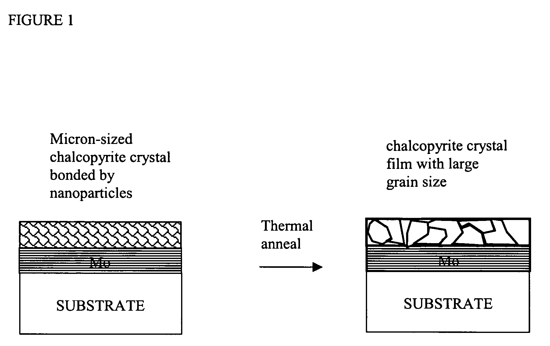
[0042]A Compound semiconductor CuInSe2 was prepared by reacting equivalent mole of Cu powder, indium shots with two mole equivalent amount of selenium pellets at temperature of 350° C. under a pressured nitrogen atmosphere (50 Psi) for 2 hours. The formed CuInSe2 crystal material was crashed into fine power of about 300 μm, and ball milled into micro-sized fine power with the average particle size of about 0.6 μm suspended in mixture solvent of butyl acetate / anisole (1:1 v / v) with the concentration of 40% (g / mL). Thus formed ink is drop-coated on a molybdenum (0.6 μm) coated soda lime glass with the final black film thickness of 2.0 μm upon drying at 160° C. under vacuum. Dektak surface profile shows the film is not smooth with the variation of 30%. The film is further annealed at argon atmosphere at 300° C. for 2 hours, and the film was peeled off by a scotch tape test. No solar cell device was made as the result of loose film morphology.

example 2

[0043]A direct formation of CuInGaSe2 nanoparticle through a chemical reaction in the mixture solvent of dichlorobenzene and trioctyl phophine was carried out:

Cu(acac)2+In(acac)3++2Se→CuInSe2  (1)

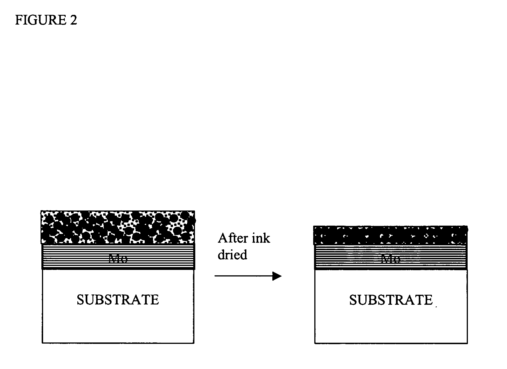
[0044]The formed nanoparticle CIS was purified through a repeated dissolving and precipitation method in dichlorobenzene and ethanol, and finally stabilized in a capping agent, oleylamine. The ink could be used for screen printing, brushing, dipping, spin-coating, ink-jet printing, or rod-coating to form film of CuInSe2 film. By a simple rod-coating on a Mo coated soda lime glass substrate, and dried under vacuum oven at 150° C. for 3 hours, a smooth film (non-uniformity2, with the performance of Voc=0.421 V; Jsc=18.8 mA / cm2, Field effect %=40%; Energy conversion efficiency=3.2%.

example 3

[0045]A CIS semiconductor ink was formulated by combining the following ingredients in a solvent vehicle:

CuInSe2 particles as prepared and ball milled to 0.6 μm size: 60 parts by weight

Nanosized CuInSe2 as prepared in Example 2: 30 parts by weight

Oleyl amine: 3.0 parts by weight

Anisole: 60 parts

Butyl acetate: 60 parts

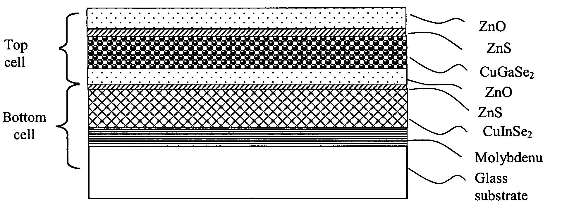
[0046]By using the above formulated ink, a standard solar cell was made according to the description of Example 2, and the following structure: SLG Glass / Mo (0.6 μm) / CIS 2.0 um / CdS (50 nm) / i-ZnO 60 nm / ZnO:Al (0.5 μm) showed photovoltaic effect under the illumination of 1.5 AM standard condition with the irradiance of 1000 W / m2, with the performance of Voc=0.491 V; Jsc=31.8 mA / cm2, Field effect %=57%; Energy conversion efficiency=9.1%.


PUM

PropertyMeasurementUnit
sizeaaaaaaaaaa
sizeaaaaaaaaaa
sizeaaaaaaaaaa

Abstract

Semiconductor ink is disclosed for use in printing thin film solar cell absorber layer. The semiconductor ink is particularly useful in fabricating multi junction tandem solar cell wherein a high bandgap absorber layer as the top cell and a lower band gap absorber layer as the bottom cell. The ink contains ingredients of IB-IIIA-VIA compound with micron-sized semiconductor as the main building “bricks” and nano-sized semiconductor as the binder to fulfill the formation of smooth semiconductive film with micron-sized crystal grain size. Thus formed ink can be used in direct printing for the fabrication of low cost high performance solar cells.

Description

BACKGROUND OF THE INVENTION[0001]1. Field of the Invention[0002]The present invention relates generally to semiconductive ink compositions, and more particularly, to compositions and methods for printing thin films of IB-IIIA-VIA compound semiconductive material useful in manufacturing thin film solar cells, and particularly monolithically linked or mechanically stacked tandem solar cells with improved efficiency and lowered cost.[0003]2. Description of the Related Art[0004]Copper indium diselenide and its derivatives of gallium and sulfur substituted compounds can be generalized as CuInxGa1-xSe2S2-y (for 0≦x≦1, 0≦y≦2), and can often be called CIS, CIGSe or CIGSeS. They are IB-IIIA-VIA semiconductor material and are widely used in thin film solar cells, due to their favorable electrical and optical properties, stability, and energy conversion efficiency. The chalcopyrite material is a tetrahedrally-bonded semiconductor, with a bandgap varying continuously with x from about 1.0 eV fo...

Claims


Application Information

Patent Timeline
Patent Type & Authority Applications(United States)
IPC IPC(8): H01L31/032H01B1/20
CPCH01L21/02568H01L21/02601H01L21/02628Y02E10/541H01L31/0725H01L31/0749H01L31/0322Y02P70/50
Inventor LI, XIAO-CHANG CHARLES
Owner GUANMAT OPTOELECTRONIC MATERIALS (JIANGXI) INC
Why Eureka
Try Eureka