Bioprinted Nanoparticles and Methods of Use

Inactive Publication Date: 2011-07-21
DREXEL UNIV
View PDF10 Cites 141 Cited by
  • Summary
  • Abstract
  • Description
  • Claims
  • Application Information

AI Technical Summary

Benefits of technology

[0024]A process for manufacturing complex structure is described. The process includes the steps of designing a printable structure via a computer-operable software application, converting the designed structure into a heterogeneous material and multi-part assembly model, and printing the designed structure using a device comprising a plurality of differentiated, specialized nozzles, wherein at least one of the nozzles is specialized for the deposition of at least one material comprising a magnetic particle. In one embodiment, the structure is a tissue scaffold. In another embodiment, the material comprising a magnetic particle is a magnetically labeled cell. In another embodiment, the material comprises a magnetically labeled bioactive factor. In another embodiment, the process further comprises repositioning the magnetically labeled bioactive factor on or within the structure after initial deposit via a magnetic field after printing the magnetically labeled bioactive factor. In another embodiment, the process further comprises repositioning the material comprising a magnetic particle via a magnetic field after printing at least one material comprising a magnetic particle. In another embodiment, the magnetic particle is a superparamagnetic nanoparticle. In another embodiment, the superpa

Problems solved by technology

These techniques are very limited in their level of sophistication.
Organized, heterogeneous cellular structures are very difficult to create, and impossible to create at the complexity level of an organ using standard techniques.
Seeding these kinds of scaffolds may not be enough to stimulate the cells into responding in the desired manner.
Unfortunately, many Solid Freeform Fabrication (SFF) techniques are not biologically friendly, using techniques that cannot handle a wide range of wet materials, gels or solutions.
Also, many SFF techniques utilize harsh solvents, high temperatures, high pressures, and other factors that are not conducive to biological systems.
Many SFF techniques, such as stereolithography, fused deposition methods, and powder/binder-based techniques, are capable of creating tissue scaffolds, but cannot directly deposit cells or biological factors into the scaffold.
This process was designed for the purpose of constructing bone implants, not to provide a flexible process of creating various types of organs or biologically/chemically integrated systems and thus has several disadvantages with respect to construction of tissue engineering devices.
For example, the method is limited in materials since soft, gel-like materials cannot be used as scaffold layers.
This is a problem since many biological parts are soft or wet.
Thus, it is difficult to have two or more different materials within the same layer level.
Accuracy and recalibration is an issue as well since the scaffold layers are moved from station to station.
Thus, although a simple scaffold can be created by this method, a complex scaffold with controlled concentration gradients is difficult, if not impossible, to create.
This is a serious disadvantage since cells are very responsive to even the slightest differences in concentration gradients.
This is not a very practical system for depositing multiple, heterogeneous materials such as different types of cells and growth factors all within the same scaffold layer.
Further, it is difficult to take a multiple part assembly of STL files and print out a complex, biologically designed scaffold utilizing this method.
Thus, there are limitations in this method with respect to the CAD integration aspect as well.
This system also uses a single nozzle and does not incorporate CAD, thus being limited to simple designs written in Microsoft Qbasic.
This system is not capable of creating heterogeneous designs within a single layer.
Thus, this system is sufficient for creating basic scaffolds, but falls short of being able to create intricate scaffolds containing both biomimetic and non-biomimetic features.
This system utilizes a single-nozzle deposition system which has fine resolution, but is limited because of the glass capillary used for deposition.
The glass capillary limits the range of viscosities that are usable due to pressure limits, and also limits the types of solutions and suspensions that can be deposited due to clogging.
Also, the single nozzle system makes multi-material, heterogeneous deposition difficult.
It is unclear whether this system can be utilized to produce multi-part, heterogeneous STL files.
This single nozzle process also makes constructing complex parts very difficult, and limits the diverse range of materials available for deposition.
In addition, there are serious limitations with their disclosed multi-nozzle system which uses the same type of syringe thus limiting the types of materials that can be de

Method used


Image

  • Bioprinted Nanoparticles and Methods of Use
  • Bioprinted Nanoparticles and Methods of Use
  • Bioprinted Nanoparticles and Methods of Use

Examples


experimental examples

[0093]The invention is further described in detail by reference to the following experimental examples. These examples are provided for purposes of illustration only, and are not intended to be limiting unless otherwise specified. Thus, the invention should in no way be construed as being limited to the following examples, but rather, should be construed to encompass any and all variations which become evident as a result of the teaching provided herein.

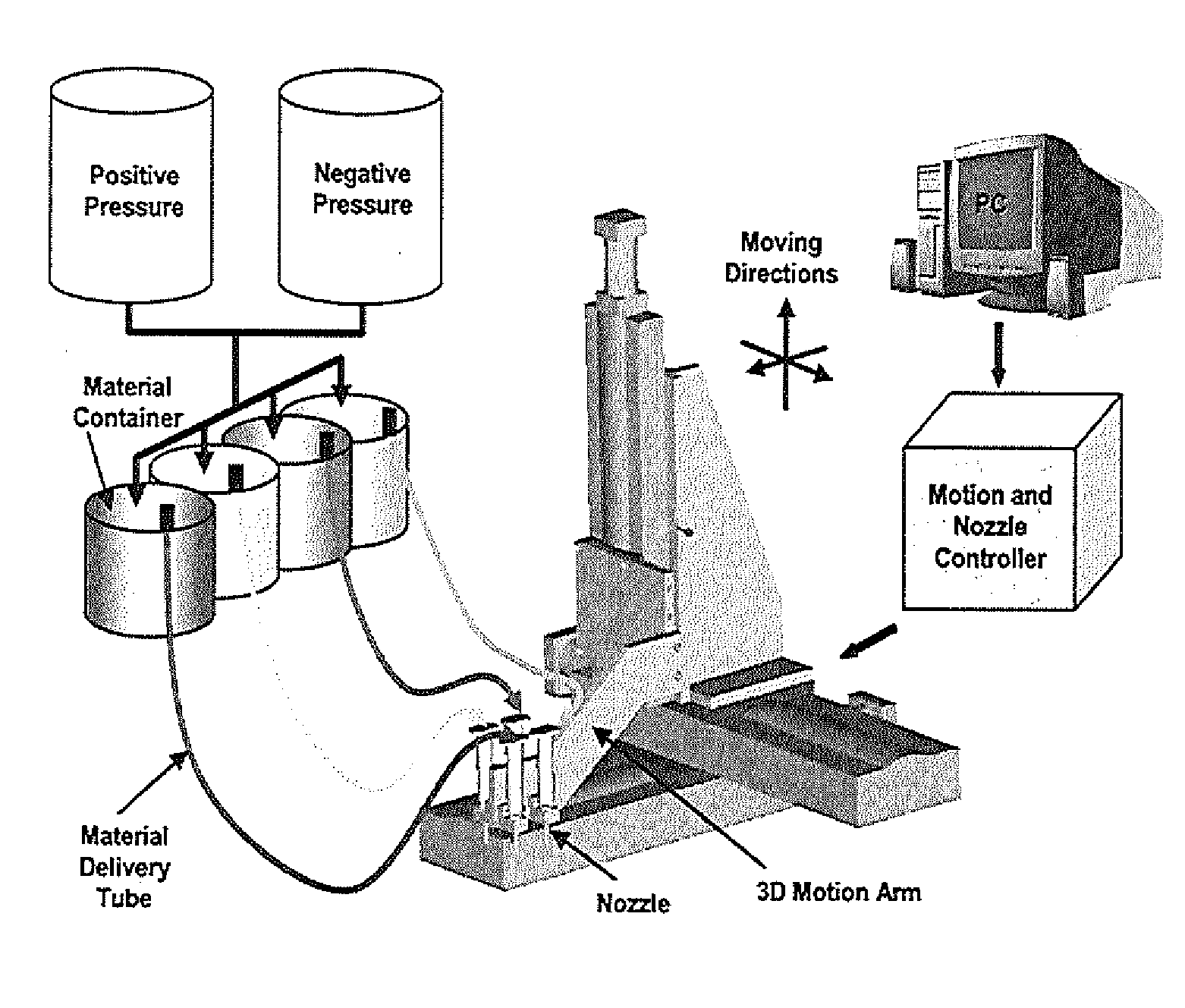
[0094]The apparatus depicted in FIG. 2 was used to construct various three-dimensional biopolymer based tissue scaffolds. For example, shown in FIG. 7 are, several three-dimensional hydrogel scaffolds (10 layers, calcium alginate), extruded as a 3% (w / v) alginate filament within a cross-linking solution (FIG. 3a) and simple alginate geometrical pattern (FIG. 3b). Depending upon the size of the syringe nozzle, the pressures used, and the type of deposition method (extrusion), alginate filaments within the 30-40 micron range (FIG. 3c) ...

example 1

Nanoparticle Uptake and Cell Viability

[0096]The following materials and methods were used in Example 1.

Chemical Formulation

[0097]Sodium alginate powder (FMCBioPolymer, Drammen, Norway) was dissolved in deionized water at 0.5, 1, 2 and 3% w / v concentrations. An ionic cross-linking solution was prepared by dissolving calcium chloride, CaCl2 (BDH Chemicals, Poole, UK), in deionized water. NanoArc magnetic iron oxide nanoparticles (Alfa Aesar, Ward Hill, Mass.) of 20-40 nm in diameter were used in all experiments. Sodium alginate-magnetic nanoparticle solutions were prepared by vigorously mixing sodium alginate with increasing concentrations of iron oxide nanoparticles to achieve a homogeneous nanoparticle distribution.

Cell Culture

[0098]Porcine aortic endothelial cells (PAEC) were isolated by the collagenase dispersion method and maintained in low glucose Dulbecco's Modified Eagle's medium (DMEM) supplemented with 5% fetal bovine serum, 1% penicillin-streptomycin, and 2% glutamine (Invi...

example 2

Effects of Printing Parameters and Scaffold Properties

[0117]The following materials and methods were used in Example 2.

Scaffold Material

[0118]Sodium alginate powder (FMCBioPolymer, Drammen, Norway) was dissolved in deionized water at 1, 2 and 3% w / v concentrations. An ionic cross-linking solution was prepared by dissolving calcium chloride, CaCl2 (BDH Chemicals, Poole, UK), in deionized water. NanoArc magnetic iron oxide nanoparticles (20-40 nm diameter, Alfa Aesar, Ward Hill, Mass.) were used in all experiments. Sodium alginate-magnetic nanoparticle solutions were prepared by vigorously mixing sodium alginate with increasing concentrations of iron oxide nanoparticles to achieve a homogeneous nanoparticle distribution.

Cell Culture

[0119]PAEC were isolated by the collagenase dispersion method and maintained in low glucose Dulbecco's Modified Eagle's Medium (DMEM) supplemented with 5% fetal bovine serum, 1% penicillin-streptomycin and 2% glutamine (Invitrogen, Carlsbad, Calif.). Cultur...


PUM

PropertyMeasurementUnit
Diameteraaaaaaaaaa
Lengthaaaaaaaaaa
Lengthaaaaaaaaaa

Abstract

The present invention provides compositions and methods that combine the initial patterning capabilities of a direct cell printing system with the active patterning capabilities of magnetically labeled cells, such as cells labeled with superparamagnetic nanoparticles. The present invention allows for the biofabrication of a complex three-dimensional tissue scaffold comprising bioactive factors and magnetically labeled cells, which can be further manipulated after initial patterning, as well as monitored over time, and repositioned as desired, within the tissue engineering construct.

Description

CROSS-REFERENCE TO RELATED APPLICATIONS[0001]The present invention claims priority to U.S. Provisional Patent Application No. 61 / 285,750, filed Dec. 11, 2009, the entire disclosure of which is incorporated by reference herein as if set forth herein in its entirety.STATEMENT REGARDING FEDERALLY SUPPORTED RESEARCH OR DEVELOPMENT[0002]This invention was made with government support under grant number CMMI-1038769 awarded by the National Science Foundation. The government has certain rights in the invention.BACKGROUND OF THE INVENTION[0003]Tissue engineering is an interdisciplinary field that uses engineering and life science principles to advance our knowledge of tissue growth, which is then applied toward the development of biological tissues, such as biological tissue substitutes far use in restoring organ function (Langer and Vacanti, 1993, Science 260:920).[0004]Most tissue engineering techniques basically consist of seeding a tissue scaffold or culture dish with cells that are gro...

Claims


Application Information

Patent Timeline
IPC IPC(8): C12N5/071C12M3/04B05D5/12H01F1/00A61L33/00B05C11/00
CPCA61L27/38A61L27/44A61L27/50A61L27/54A61L2300/80H01F1/0054C12N5/0006C12N5/0068C12N2533/74H01F1/0045B82Y25/00
Inventor CLYNE, ALISA MORSSBUYUKHATIPOGLU, KIVILCIMCHANG, ROBERTSUN, WEI
Owner DREXEL UNIV
Why Eureka
Try Eureka