[0014]In view of the foregoing, this invention is directed to the production of metallized
radiant barrier materials with low emissivities, improved resistance of the emissive surface to
environmental degradation, and chemical and electrical functionality of the barrier structure. All insulation applications,
ranging from
building insulation to apparel with
heat management properties, are intended to be covered.
[0016]According to another aspect of the invention, the
metal layer, in particular aluminum, is preferably exposed to an
oxygen-
plasma-induced passivating step in vacuum, immediately after deposition, to improve its
corrosion resistance. In conventional radiant-barrier metallization processes, the substrate film is metallized in a
vacuum chamber and then unwound under atmospheric conditions to be slit and coated with a
lacquer.
Exposure of the freshly metallized aluminum to air that contains both
oxygen and
moisture leads to the formation of hydrated aluminum oxides with poor corrosion resistance. In the invention, the corrosion resistance of the aluminum layer is maximized by forming a pure Al2O3
barrier layer on the
metal surface. Unlike hydrated aluminum
oxide, which may exhibit various degrees of corrosion resistance based on the ambient level of
humidity when the metallized layer is taken out of the
vacuum chamber, the in-situ-formed aluminum
oxide of the invention is uniform, non-porous and
corrosion resistant. Therefore, the pinhole-free protective
polymer coating is combined with the formation of a high quality Al2O3-
barrier layer to protect the aluminum radiant-
barrier layer from corrosion-related degradation.
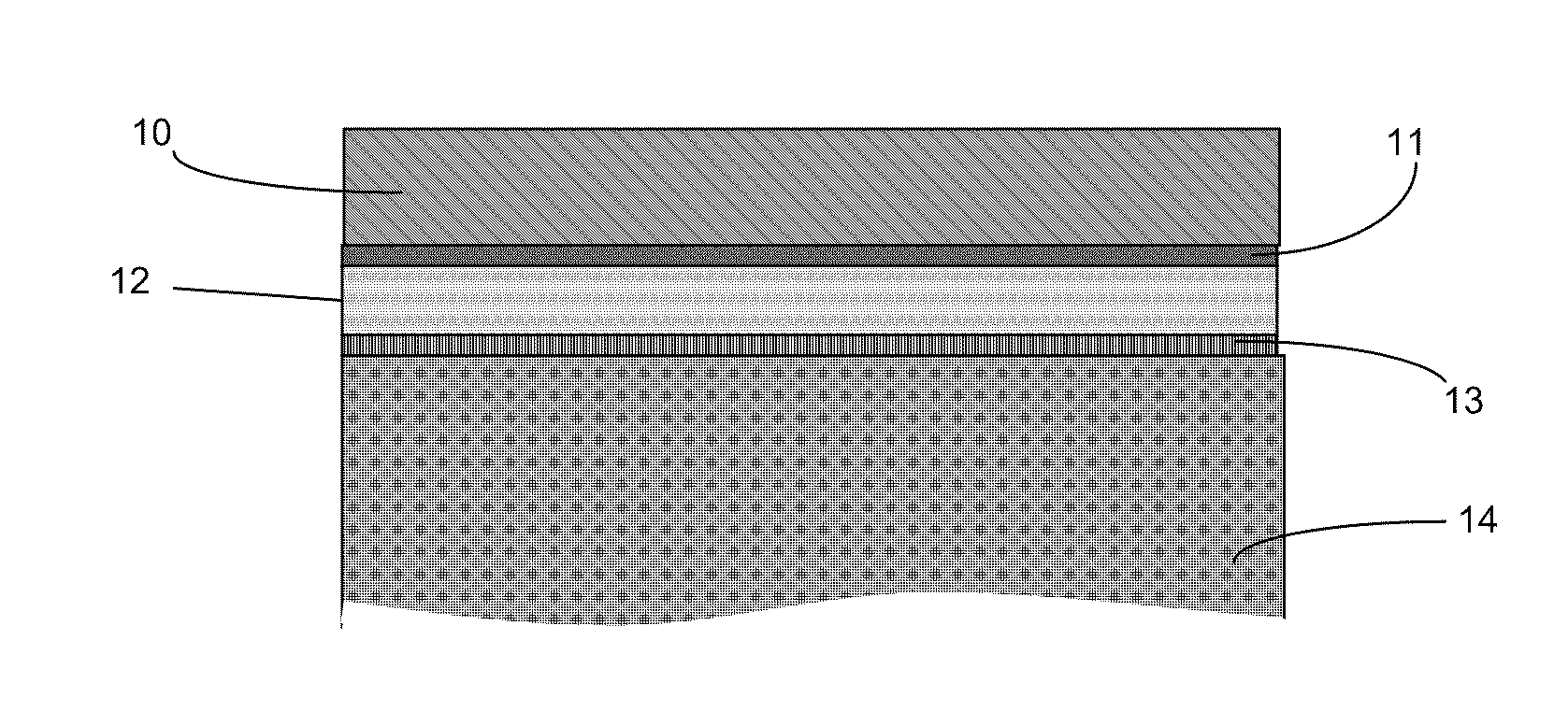
[0017]According to yet another aspect of the invention, a leveling polymeric layer may be deposited between the substrate and the aluminum layer in order to improve the corrosion resistance of the metallized aluminum layer as well as its
mechanical integrity. When an aluminum layer is deposited on various substrates, the measured emissivity value reflects the average aluminum thickness and continuity of the aluminum layer across the substrate.
Low emissivity values are obtained with flat and level
polymer film substrates, while higher values result from materials that have
high surface micro-roughness and discontinuous surfaces, such as woven and woven substrates. We found that when polymer-film substrates such as
polyethylene,
polypropylene and
polyester are metallized, even with
low emissivity values of ∈=0.03 to ∈=0.04, the metallized layer has a large number of microscopic pinholes, the density of which can vary dramatically from one polymer film to another based on their
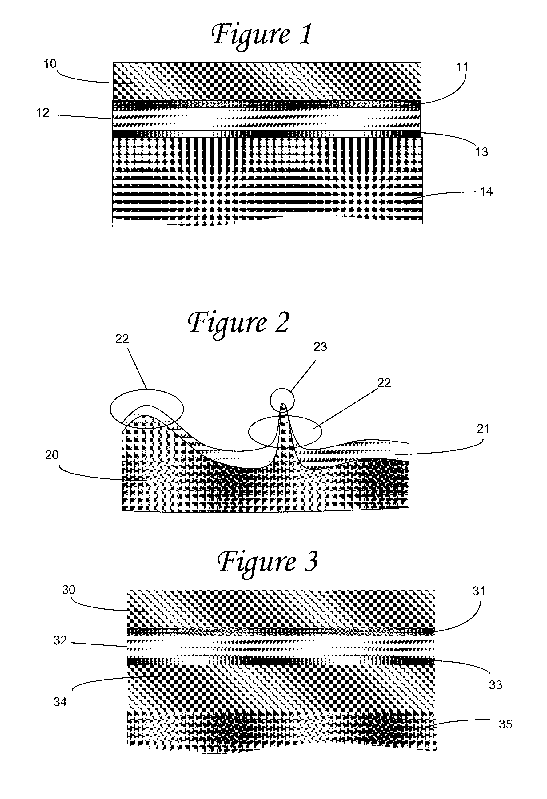
surface roughness. The pinholes are usually located on the peak of film fibral features that protrude above the film surface and overheat during the
metal deposition, as well as at the top of additives that bloom onto the film surface (antioxidants and slip agents). The pinholes represent areas where corrosion sites can initiate during the life of the product. Furthermore, the metallized layer around a feature that protrudes above the film surface has a significantly lower thickness (and higher emissivity) than the average aluminum thickness. This, combined with the presence of a pinhole, will accelerate the corrosion of the aluminum layer and lead to high levels of degradation over the life of the product. We found that a leveling
polymer coating deposited on the
substrate surface has several benefits that contribute to the quality and performance stability of the metallized aluminum layer. Specifically, it reduces the level of micro-roughness, which improves the thickness uniformity of the metal layer. Also, the
electron-beam cross-polymerized layer has superior thermomechanical properties than the substrate resulting in a lower number of pinholes. Finally, the leveling layer produces greater adhesion of the metallized aluminum, which in turn minimizes
delamination and microcracking, all of which lead to loss of performance.
[0018]According to another aspect of the invention, a non-specular durable and high-performance radiant-barrier structure is produced that eliminates occupational
hazard issues that can result both during the installation as well as the operation of such specular radiant-barrier material due to the reflection of
bright light from its surface, which can temporarily blind an installer or operator. A
polymer coating that has a diffuse surface in the
visible spectrum is deposited on the substrate. When metallized, this type of surface results in a hazy metallic layer that is void of specular metallic glint. In fact in same cases the surface texture can be controlled to produce a subtle
color shift which is attractive and pleasing to the eye. A key part of this invention is the creation a surface that eliminates the metallic without significantly changing the emissivity value.
[0021]Another aspect of this invention is the superposition of
chemistry on the protective functional layer that reduces or eliminates growth of
bacteria, mold, fungi as well as other contaminants such as fingerprints during the installation process.
Radiant barrier material used in environments of high temperature and
humidity can grow
bacteria, mold and fungi that will eventually add an absorbing layer that reduces radiant-barrier performance. The
chemistry of the protective functional layer is formulated to
resist bacteria growth as well as produce hydrophobic and oleophobic functionality to minimize
wetting of the functional polymer layer.
[0022]Yet another aspect of the invention is the formation of a barrier structure that has an electrical functionality. Specifically, given their
low emissivity, most radiant-barrier materials used in housing applications are composed of a continuous metal layer that is
electrically conductive. This creates two different problems: a) the
radiant barrier (or reflective insulation) when placed in the
attic and walls of a structure can inhibit cellular communications by blocking the RF signals; and b) during installation or at some point during the life of the a
radiant barrier product, the metallized surface can come into contact with an exposed
power cable (live wire), which can cause
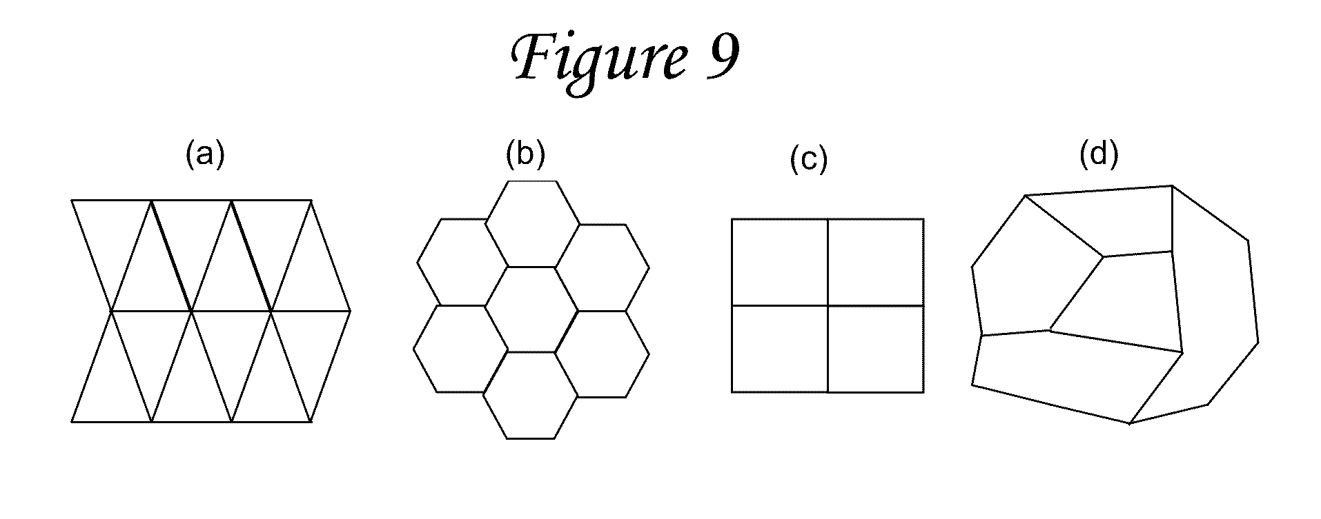
electric shock or start a fire. We found that one method to resolve both of these problems is to segment the metallized layer into small sections that prevent conduction along the radiant-barrier sheet and allow RF frequencies to transmit through the barrier. Another approach that resolves only the second problem is to control the thickness of the metal layer so that it has “self-healing” or “clearing” properties. Both of these terms are commonly used in the metallized
capacitor industry to describe the ability of a
capacitor comprising metallized electrodes and a polymer film
dielectric to recover from an electrical short by a process where the
thin metal electrode melts away from the location of the short, much like a fuse (see A. Yializis, Handbook of
Solid State Batteries & Capacitors, Edited by M. Z. A. Munshi, World Scientific, 1995). The radiant barrier self-healing process is different from that of metallized film capacitors, but it can be equally effective in preventing an
electric shock or a fire.

