
Material for forming underlayer film for lithography, composition for forming underlayer film for lithography, underlayer film for lithography and pattern forming method

a technology of lithography and composition, applied in the direction of photosensitive material processing, photomechanical equipment, instruments, etc., can solve the problems of difficult to achieve resist pattern having a film thickness sufficient for processing a substrate, and the intrinsic limitation of light source wavelength, so as to achieve excellent heat resistance and etching resistance

Active Publication Date: 2018-04-12
MITSUBISHI GAS CHEM CO INC
View PDF2 Cites 0 Cited by
  • Summary
  • Abstract
  • Description
  • Claims
  • Application Information

AI Technical Summary

Benefits of technology

The present invention provides materials and compositions for creating an underlayer film for lithography that can withstand heat and etching during a wet process. The invention also includes a pattern forming method using these materials to create highly precise patterns.

Problems solved by technology

In lithography using exposure to light, which is currently used as a general-purpose technique, the resolution is now approaching the intrinsic limitation associated with the wavelength of the light source.
However, as the resist pattern is made finer and finer, there arise a problem of resolution and a problem of collapse of the resist pattern after development, and therefore there is demanded for making a resist film thinner.
If the resist film is merely made thinner, however, it is difficult to achieve the resist pattern having a film thickness sufficient for processing a substrate.

Method used


Image

  • Material for forming underlayer film for lithography, composition for forming underlayer film for lithography, underlayer film for lithography and pattern forming method
  • Material for forming underlayer film for lithography, composition for forming underlayer film for lithography, underlayer film for lithography and pattern forming method
  • Material for forming underlayer film for lithography, composition for forming underlayer film for lithography, underlayer film for lithography and pattern forming method

Examples


synthesis example 1

Synthesis of bis(4-cyanatophenyl)phenylmethane (Hereinafter, Referred to as “B-CN”.)

[0185]In 100 mL of tetrahydrofuran were 27.6 g (100 mmol) of bis(4-hydroxyphenyl)phenylmethane (produced by Wako Pure Chemical Industries, Ltd.) and 28.3 g (280 mmol) of triethylamine, to provide solution 1.

[0186]Solution 1 was dropped in a mixed liquid of 46.2 g of a solution of 18.4 g (300 mmol) of cyanogen chloride in methylene chloride with 100 mL of tetrahydrofuran at −10° C. over 1.5 hours. Once the termination of the reaction was confirmed, the reaction liquid was concentrated, and the resulting crude product was dissolved in 300 mL of methylene chloride. The resultant was washed with 1 M hydrochloric acid and distilled water, and dried over anhydrous magnesium sulfate. Methylene chloride was distilled off to thereby provide 30.0 g of objective bis(4-cyanatophenyl)phenylmethane. The structure of the compound obtained as described above was identified by NMR spectroscopy.

[0187]The IR spectrum o...

synthesis example 2

Synthesis of tris(4-cyanatophenyl)-1,1,1-methane (Hereinafter, Referred to as “TRPCN”.)

[0190]In 500 g of tetrahydrofuran were 0.17 mol (in terms of OH group) of tris(4-hydroxyphenyl)-1,1,1-methane (produced by Tokyo Chemical Industry Co., Ltd.) and 0.57 mol of triethylamine, to provide solution A. Next, solution A was dropped in a solution, in which 0.67 mol of cyanogen chloride, 175 g of methylene chloride and 500 g of chloroform were mixed, at −5° C. over 1.5 hours and stirred for 30 minutes, and thereafter a mixed solution of 0.08 mol of triethylamine and 15 g of chloroform was dropped therein and further stirred for 30 minutes to terminate the reaction. After the reaction liquid was subjected to filtration, the resulting filtrate was washed with 800 ml of 0.1 N hydrochloric acid, thereafter repeatedly washed with 800 ml of 2.5% brine four times, and finally washed with 800 mL of water. Sodium sulfate was added thereto to remove the water content by adsorption, and thereafter the...

synthesis example 3

Synthesis of Dibenzoxanthene Dcyanate (Hereinafter, Referred to as “BisN-CN”.)

[0194]To a container having an inner volume of 300 ml, equipped with a stirrer, a condenser and a burette, were charged 32.0 g (200 mmol) of 2,6-naphthalenediol (reagent produced by Sigma-Aldrich), 18.2 g (100 mmol) of 4-biphenylaldehyde (produced by Mitsubishi Gas Chemical Company, Inc.) and 100 ml of 1,4-dioxane, 5 ml of 95% sulfuric acid was added thereto, and the reaction liquid was stirred at 100° C. for 6 hours to perform a reaction. Then, the reaction liquid was concentrated, 50 g of pure water was added thereto to precipitate a reaction product, and the resultant was cooled to room temperature followed by filtration for separation. The resulting solid was subjected to filtration, dried, and thereafter separated and purified by column chromatography to thereby provide 30.5 g of an objective compound (BisN-1) represented by the following formula.

[0195]Herein, the following peaks were observed by 400 ...


PUM

PropertyMeasurementUnit
Lengthaaaaaaaaaa
Lengthaaaaaaaaaa
Compositionaaaaaaaaaa

Abstract

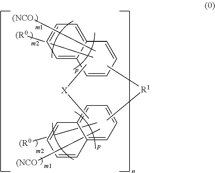
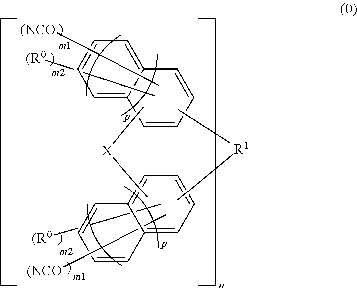
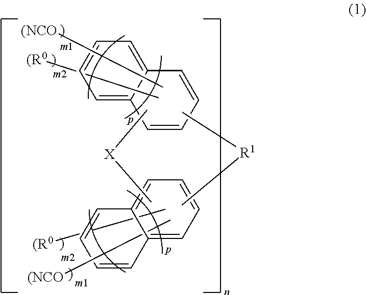
A material for forming an underlayer film for lithography, in which a compound represented by the following formula (0) is used.(in formula (0), each X independently represents an oxygen atom or a sulfur atom, or a non-crosslinked state, R1 represents a 2n-valent group having 1 to 30 carbon atoms, or a single bond, each R0 independently represents a straight, branched or cyclic alkyl group having 1 to 30 carbon atoms, an aryl group having 6 to 30 carbon atoms, a straight, branched or cyclic alkenyl group having 2 to 30 carbon atoms, a thiol group, a halogen group, a nitro group, an amino group, a carboxylic acid group or a hydroxyl group, the alkyl group, the alkenyl group and the aryl group each optionally include a cyanato group, a thiol group, a halogen group, a nitro group, an amino group, a carboxylic acid group, a hydroxyl group, an ether bond, a ketone bond or an ester bond, each m1 is independently an integer of 0 to 4, in which at least one m1 is an integer of 1 to 4, each m2 is independently an integer of 0 to 3, n is an integer of 1 to 4, and each p is independently 0 or 1.)

Description

TECHNICAL FIELD[0001]The present invention relates to a material for forming an underlayer film for lithography, containing a compound of a specified structure, a composition for forming an underlayer film for lithography, including the material, an underlayer film for lithography, formed using the composition, and a photoresist pattern forming method (resist pattern method or circuit pattern method) using the composition.BACKGROUND ART[0002]Semiconductor devices are manufactured through microfabrication by lithography using a photoresist material. Such semiconductor devices are required to be made finer by a pattern rule in accordance with the increase in integration degree and the increase in speed of LSI in recent years. In lithography using exposure to light, which is currently used as a general-purpose technique, the resolution is now approaching the intrinsic limitation associated with the wavelength of the light source.[0003]A light source for lithography, for use in forming ...

Claims


Application Information

Patent Timeline
IPC IPC(8): G03F7/11C07C261/02C07D311/78C07C39/15C09D173/00C09D165/00G03F7/16G03F7/20G03F7/38G03F7/32G03F7/039H01L21/308
CPCG03F7/11C07C261/02C07D311/78C07C39/15C09D173/00C09D165/00G03F7/162G03F7/168G03F7/2037G03F7/38G03F7/322G03F7/039H01L21/3081H01L21/3086G03F7/0045G03F7/20G03F7/26
Inventor OKADA, KANAMAKINOSHIMA, TAKASHIECHIGO, MASATOSHIHIGASHIHARA, GOOKOSHI, ATSUSHI
Owner MITSUBISHI GAS CHEM CO INC
Learn More