
Ultrasonic impact machining of body surfaces to correct defects and strengthen work surfaces

a technology of body surface and machining, which is applied in the direction of mechanical vibration separation, furnaces, heat treatment apparatus, etc., can solve the problems of inability to disclose a feasible system, insufficient power delivery of massive metal workpiece bodies to effectively, and increase strength, etc., to achieve excellent power transfer efficiency, increase output power, and high velocity

Inactive Publication Date: 2005-08-23
PROGRESS RAIL SERVICES
View PDF26 Cites 103 Cited by
  • Summary
  • Abstract
  • Description
  • Claims
  • Application Information

AI Technical Summary

Benefits of technology

[0024]Impact power of small diameter needles moving independently from the driving transducer to the workpiece in a free axial mode of movement permits very high velocities and high energy derived from the transducer periodic ultrasonic power source. This results in enough impact power for both plastic surface and sub-surface structural reconfiguration of heavy metallic objects to significant depths. Because of the small impact area, short impact time, duty cycle and the heat absorbing characteristics of the metallic workpiece, surprisingly, during ultrasonic impact, the workpiece is rapidly heated and cooled at a localized area at the point of the impact and machined at ambient temperatures. The workpiece after machining remains then at an ambient temperature.
[0025]A transducer to workpiece interface is established by operation of sets of impacting needles which rebound from the work surface to the periodically ultrasonic oscillating driving anvil. This in effect produces a broad-band work interface characteristic that maximizes working power output transferred by the separate very high velocity needles instantaneously impacting the surface from the periodically oscillating ultrasonic power generating source in accordance with the advantageous kinetic energy impact relationship (W=mv2 / 2) utilized by this invention. Thus, the kinetic energy delivered from the high velocity of the free flying impact needle, being a function of v2, is much larger than possible with the direct impact of the transducer horn taught by Jacke and other direct transducer to workpiece interfacing systems of the prior art mentioned above.
[0027]Moreover, the impact includes the ultrasonic oscillations of the impact needle in the surface layer of the material being treated together with the ultrasonic transducer head impact surface during individual ultrasonic impact. Such ultrasonic oscillations in turn initiate in the treated material power ultrasonic waves propagation of which creates individual effects of reduction in deformation resistance and relaxation in the material being treated.
[0029]Critical to the output power delivery is a series of mechanically interconnected serial stages in the working transducer assembly, which is small in size for portable and manual operations and thus adaptable to use in restricted spaces, for providing excellent power transfer efficiency from a basic periodic ultrasonic source of power. A series of interconnected transducer stages exhibiting respective mechanical resonances harmonically related to the primary ultrasonic oscillation frequency so that a much greater multiple of that primary ultrasonic frequency thereby imparts a very high velocity to the freely moving impact needles and further produce a Q-factor amplification of the oscillating system contributing to greater output power from the available oscillator input power. Also, for efficient transfer of power from the respective operating stages of the transducer, matched instantaneous resistances are provided at the instantaneous loading moment of operation when the freely axially movable impact needle elements are driven by the transducer oscillating surface vibrating at the primary ultrasonic frequency aperiodically into the surface of the workpiece.
[0030]This mode of operation provides the novel thermal treatment to the workpiece to plasticize the surface and sub-surface metal for the impact machining improvement of the workpiece work surface strength and operating performance in the presence of working compressive forces. Thus, the thermal machining in the plastic state with impact forces compressing the workpiece (e.g. a propeller) metal surface layer produces increased compressive working force capacity expended by compressively interfacing saltwater with mechanically moving surfaces e.g. propeller blade surfaces, and the operating life is lengthened.
[0032]Accordingly, this invention provides novel ultrasonic oscillating elements and operating methods and novel ultrasonic impact machining modes for machining interfacing working surfaces of various kinds of metallic workpieces to effect plastic surface and sub-surface deformation resulting in structural changes, and increasing material hardness and service life.

Problems solved by technology

However, this teaching does not disclose a feasible system for the reworking of machined metal workpieces by ultrasonic impact machining methods wherein the machined metal surface and sub-surface thereunder is deformed to control surface texture and workpiece hardness, as does the present invention.
However, this transducer horn system cannot deliver enough power to a massive metal workpiece body to effectively penetrate any considerable distance into sub-surface areas for deforming and compressing the surface and adjacent sub-surface regions and increasing the strength of massive metal bodies, such as cast iron used in various tool embodiments for compressive confrontation of mating surfaces.
This prior art system, however, does not disclose satisfactory ultrasonic machining methods or systems or an ultrasonic transducer structure as afforded by the present invention or any structure or methods that could successfully develop and control ultrasonic energy intensity sufficient for general purpose ultrasonic impact machining by deforming both surface and sub-surface structure to a significant depth in a variety of working interface surface shapes of massive metallic bodies for compressively confronting mating surfaces.
These prior art ultrasonic transducer systems have not provided satisfactory tools, systems or methods for reworking and machining metallic work interface surfaces of various shapes employed in frictional compressive and sliding contact, such as presented in rotary bearing surfaces, brake drums as well as sliding and reciprocating engine cylinders or wedges, propellers and the like, thereby to deform surface and sub-surface structure, hardness and texture for producing longer work life while bearing increased compressive work loads.
In general, the prior art ultrasonic transducer systems have not been able to provide high enough readily controlled impact power over work interfaces of considerable surface area on metallic workpiece interfacing surfaces to precisely control both the surface hardness and texture and the adjacent sub-surface structure at significant working depths exceeding normal wear tolerances.
Thus, such prior art systems and methods do not provide substantially universal ultrasonic transducer systems and methods suitable in size, power and control for achieving work functions, such as desirable for the repair or manufacturing of metallic work interfacing surfaces for compressive confrontation with mating surfaces.
Nor is the prior art capable of plastically deforming and compressing surface and adjacent sub-surface regions to sufficient depths particularly for machining a variety of different surface configurations on massive metallic bodies thereby to attain specified end structure in both surface and sub-surface regions of a treated metallic workpiece.
For example, consider the problems of manufacturing and / or repairing a propeller having critical surface characteristics at blades, hubs and fillets of different shapes and masses, and being subject to various kinds of sub-surface defects, such as cavitation, corrosion, wear, cracks and welding stresses, which would deteriorate the reaction of marine propeller blade working surfaces in underwater compressive and sliding interface with saltwater.
There has been no known successful multi-function system or method for ultrasonic impact machining of such diverse sets of conditions as incurred in the manufacture and in-service repairs of marine propellers.
The typical prior art manufacture and repair of marine propellers is expensive and complex and must employ a series of incompatible treatment methods, such as heat treatment of the metallic workpiece in a furnace, which cause defects which deteriorate the desired service as a marine propeller.
Conventional repairs are made by heat treatments and controlled cooling cycles, grinding, machining, welding depositions, and the like, which in turn introduce new stresses, fatigue and corrosive characteristics and are expensive and time consuming.
In particular, the heat treatments are critical in the presence of transition surfaces, blade thickness variations, uneven mass distributions, etc. which tend to leave unevenly distributed thermal deformations and unfavorable residual tensile stresses that speed up corrosion, fatigue and wear failures in service, particularly in salt water environments.
It is also necessary to introduce various surface treatments after internal heat treatments, such as to supply protective coatings on propeller blades and the like, which in turn introduce surface imperfections that interfere with work surface operation.
For example, required surface characteristics may range from in-service optical smoothness to specified degrees of surface roughness necessary to anchor an outer smoothing layer, and there has been no known prior art ultrasonic machining method or system for achieving this.

Method used


Image

  • Ultrasonic impact machining of body surfaces to correct defects and strengthen work surfaces
  • Ultrasonic impact machining of body surfaces to correct defects and strengthen work surfaces
  • Ultrasonic impact machining of body surfaces to correct defects and strengthen work surfaces

Examples


Embodiment Construction

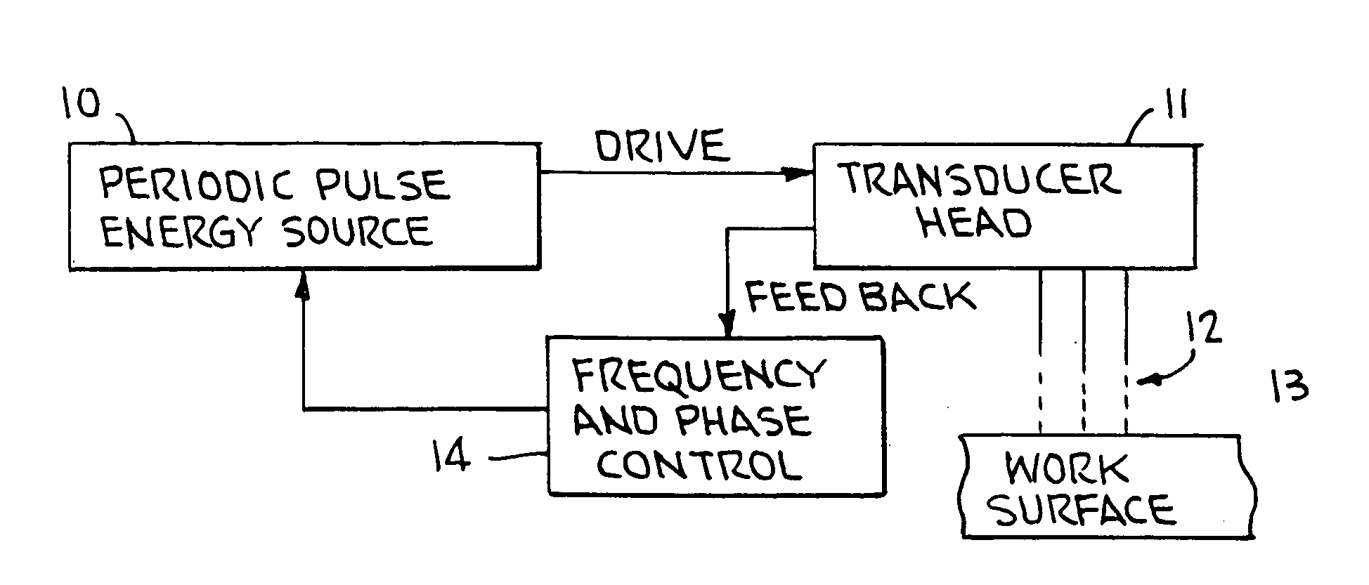
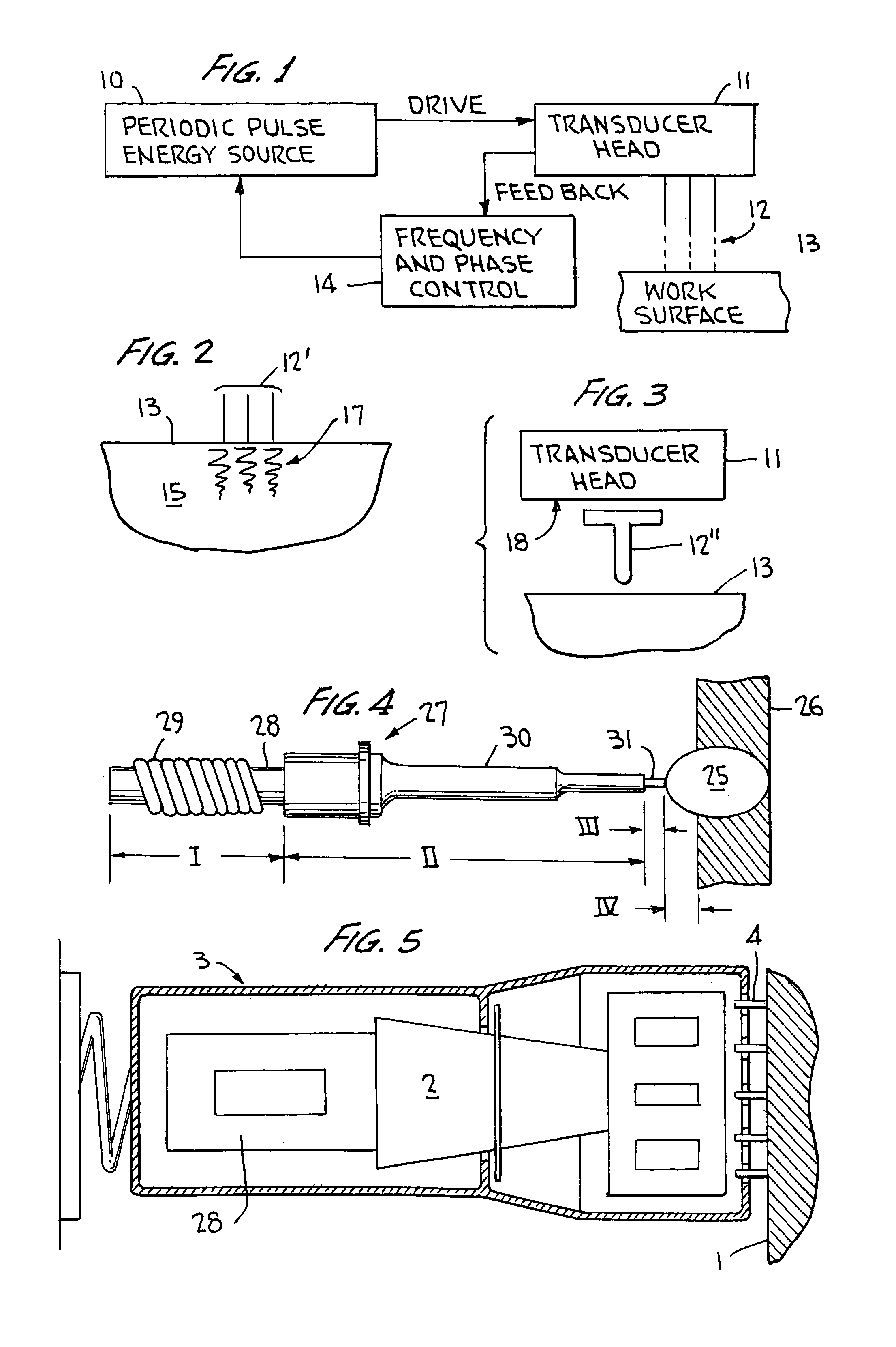
[0058]With reference to FIG. 1 of the drawings, this block system diagram identifies the ultrasonic impact operating system for treating metallic workpiece surfaces, shown as work surface 13, by employing a set of ultrasonically movable impacting elements 12, presented typically as sets of three or four spaced members, for impacting the work surface 13 under control of the ultrasonic transducer head 11. The periodic pulse energy source 10, typically operable at ultrasonic frequencies up to 100 kHz, induces oscillations into the transducer head 11, preferably subject to feedback frequency and phase control 14 processing feedback from the working transducer head 11 to aid in matching resonance characteristics of the head when working on the work surface 13 in the manner more particularly set forth in the parent applications.

[0059]In FIG. 2, the impacting element set 12′ creates at the work surface 13 and extending into the sub-surface region 17 of a metallic work body 15, plasticized ...


PUM

PropertyMeasurementUnit
Temperatureaaaaaaaaaa
Forceaaaaaaaaaa
Flow rateaaaaaaaaaa

Abstract

Metallic workpieces of diverse shapes having work surfaces which are deformed at the surface and adjacent sub-surface layers by surface impact from ultrasonic transducers employing freely axially moving impacting elements propelled and energized by a transducer oscillating surface vibrating periodically at an ultrasonic frequency. The impacting elements are propelled in a random aperiodic and controlled impact mode at different phases of the periodic oscillation cycles. The transducer may be portable and provides a series of mechanically interconnected stages having mechanical resonances harmonically related as a multiple of the primary ultrasonic frequency and have matched stage resistances under instantaneous loading when the impact elements are driven by the transducer oscillating surface into the surface of the workpiece. This mode of operation produces Q-factor amplification of the input ultrasonic power oscillator energy at the impact needles and high propulsion velocities making it possible to machine metallic workpiece bodies to greater depths for compressing the metal to increase compressive strength of the workpiece work surfaces to substantially the ultimate material strength. The impact machining is done at ambient temperatures.

Description

RELATED PATENT APPLICATIONS[0001]This application is a continuation-in-part of U.S. application Ser. No. 09 / 273,769 filed Mar. 23, 1999 now U.S. Pat. No. 6,289,736, for METHOD FOR ELECTRO-ACOUSTIC TRANSDUCER EXCITATION and U.S. application Ser. No. 09 / 653,987, filed Sep. 1, 2000 now U.S. Pat. No. 6,458,225 for ULTRASONIC MACHINING AND RECONFIGURATION OF BRAKING SURFACES, the latter application in turn being a continuation-in-part of U.S. application Ser. No. 09 / 288,020 filed Apr. 8, 1999 now U.S. Pat. No. 6,338,765, for ULTRASONIC IMPACT METHODS FOR TREATMENT OF WELDED STRUCTURES, which in turn is a continuation-in-part of U.S. application Ser. No. 09 / 145,992 filed Sep. 3, 1998 now U.S. Pat. No. 6,171,415.FIELD OF INVENTION[0002]This invention relates to methods of ultrasonic impact machining of manufactured metallic bodies of various shapes to strengthen the surfaces and correct external and internal manufacturing defects and in-service-generated fatigue defects, and related appara...

Claims


Application Information

Patent Timeline
IPC IPC(8): B06B1/02B23K13/00B23K20/10B23K9/32C21D10/00C21D7/04C21D7/00C21D9/50
CPCB06B1/0253B23K13/00B23K20/10B23K20/106B23P6/00B23P9/04C21D1/09C21D7/04C21D9/0068C21D9/32C21D9/38C21D9/40C21D10/00B23K9/32Y10T428/12472C21D9/50C21D2201/00Y10S148/902Y10S29/046Y10S72/71Y10T428/12993
Inventor STATNIKOV, EFIM S.
Owner PROGRESS RAIL SERVICES
Learn More