MEMS-based, computer systems, clock generation and oscillator circuits and LC-tank apparatus for use therein

Inactive Publication Date: 2005-12-06
RGT UNIV OF MICHIGAN
View PDF12 Cites 67 Cited by
  • Summary
  • Abstract
  • Description
  • Claims
  • Application Information

AI Technical Summary

Benefits of technology

[0102]The oscillator circuit may be a double-balanced, cross-c

Problems solved by technology

However, the technology is incompatible with silicon integrated circuit technology.
In fact, for some low-performance processors, the cost of the crystal reference itself can exceed the cost of the entire processor.
Despite the obvious and inherent advantages of integrated clock synthesis, the development of such technology has not gained much momentum.
The challenges faced are many and include the inability to generate a stable clock signal on-chip due to unavailable or poor on-chip reference technology, temperature instability, and drift.
Stability is the foremost factor limiting ubiquitous employment of monolithic clock references, since short term instability can cut into processor timing budgets and compromise performance.
However, due to device noise such as flicker and thermal noise, as well as electromagnetic interference, oscillators will deviate from this center frequency.
Minimizing this phenomenon is highly desired since it can cause a variety of problems such as reciprocal mixing in RF systems and a reduction in the usable timing budget in microcontrollers.
However, if the impulse occurs some time between peaks, it is clear that the phase of the oscillation is perturbed.
Therefore, noise introduced while the output is in this portion of the cycle will contribute significantly to the phase noise, while noise introduced at the peaks of oscillation will not contribute at all.
This function describes the time-domain regions where the oscillator is most sensitive to noise injection, and therefore results in phase noise.
However, while the signal is crossing zero, both devices are on and saturated.
Unfortunately, this corresponds to the point where the ISF function is maximized.
Thus, this simple analysis clearly indicates the reason why ring oscillators exhibit such poor phase noise performance.
The drawbacks of crystals include the fact that they are relatively expensive, large, and cannot be integrated with the transistor electronics.
In dense embedded applications, this is a significant bottleneck toward miniaturization.
Moreover, the cost of these crystals can, in fact, approach the cost of the supported integrated circuit itself.
However, as discussed previously, integrated topologies such as the ring oscillator suffer from very poor phase noise performance.
Some of the contributing factors to this can be alleviated with careful design techniques, but even under these conditions, high performance cannot be achieved.
Typically, these LC-tanks will provide a reference that is more stable than a ring oscillator, but performance is still poor due to the lack

Method used


Image

  • MEMS-based, computer systems, clock generation and oscillator circuits and LC-tank apparatus for use therein
  • MEMS-based, computer systems, clock generation and oscillator circuits and LC-tank apparatus for use therein
  • MEMS-based, computer systems, clock generation and oscillator circuits and LC-tank apparatus for use therein

Examples


first embodiment

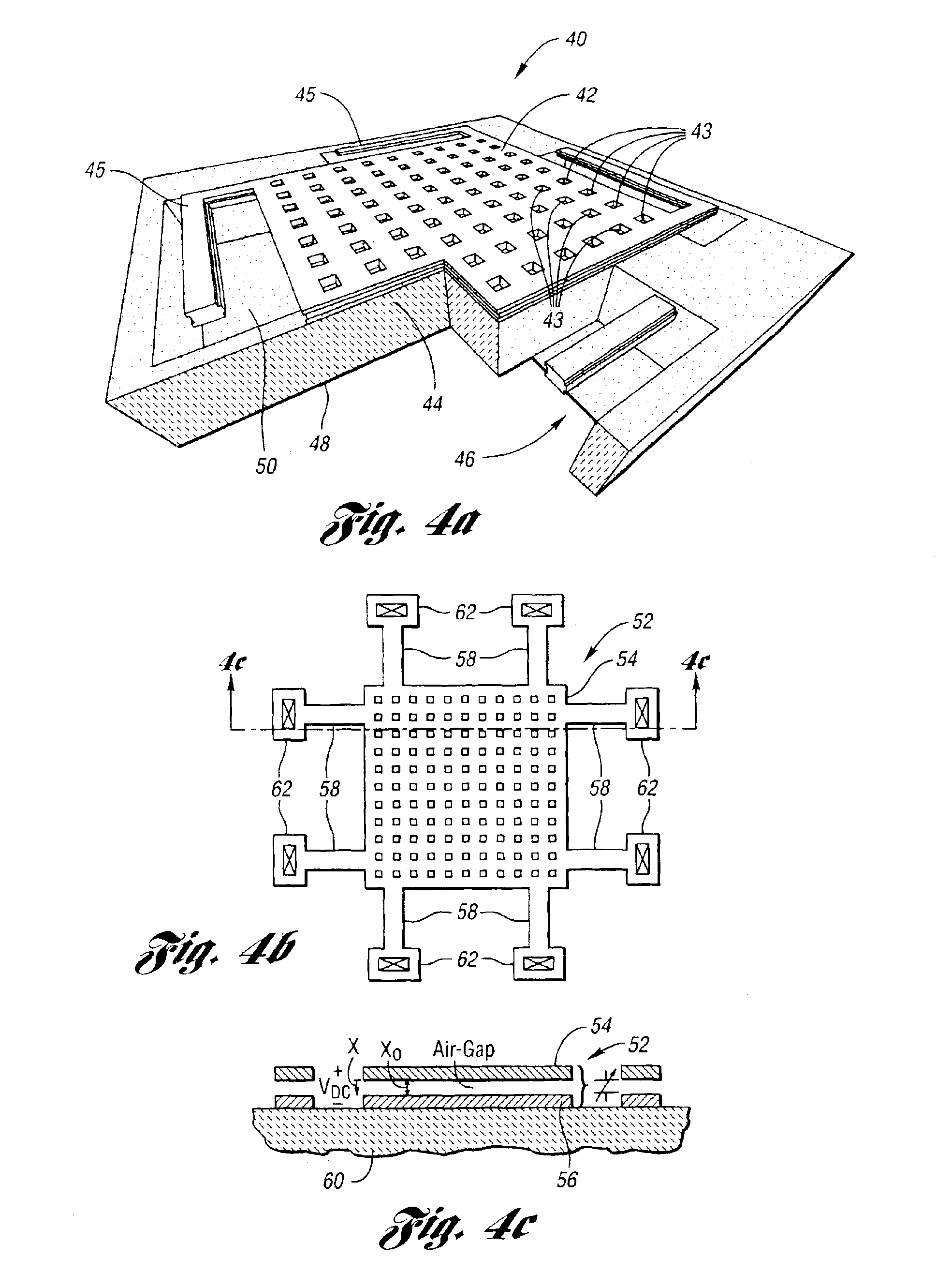
[0136]Referring now to FIG. 4a, there is illustrated a varactor fabricated upon an SOI substrate, generally indicated at 40, which focuses on the most significant drawbacks associated with previous MEMS varactor work. First, the fabrication process is CMOS compatible in order to achieve monolithic integration. Second, the tuning range is sufficiently wide. Third, the quality factor (Q-factor) is high. The varactor 40 addresses all of these issues as follows.

[0137]First, the parallel plates 42 and 44 of the varactor 40 are fabricated as part of a standard CMOS process where either the metal-insulator-metal (MiM) layers or the appropriate metal routing layers are used. Support arms 45 support the top plate 42 above the bottom plate 44. These support arms 45 may be designed in one of a variety of geometries in order to suspend the top plate 42 appropriately. No additional processing steps are required to define the structure. However, a maskless post-process is used to release the plat...

second embodiment

[0141]Referring now to FIGS. 4b and 4c, there is illustrated a varactor fabricated in a bulk CMOS process, generally indicated at 52, of the present invention. The varactor 52 includes a movable top plate 54 and a stationary bottom plate 56. The top plate 54 is supported above the bottom plate 56 by a mechanical suspension network 58 which is anchored to a substrate 60 at anchors 62.

[0142]In particular, the micromechanical varactor 52 has a parallel plate topology similar to those presented in the prior art. The varactor 52 is constructed by mechanically suspending the metal top plate 54 in air above the fixed metal bottom plate 56. The mechanical suspension network 58 provides support for the top plate 54 as shown. The varactor 52 presents a nominal capacitance set by the varactor geometry and the nominal gap between the plates 54 and 56, xo. By applying a positive DC voltage, VDC, across the plates 54 and 56, the movable top plate 54 will deflect some distance, x, due to electrost...

third embodiment

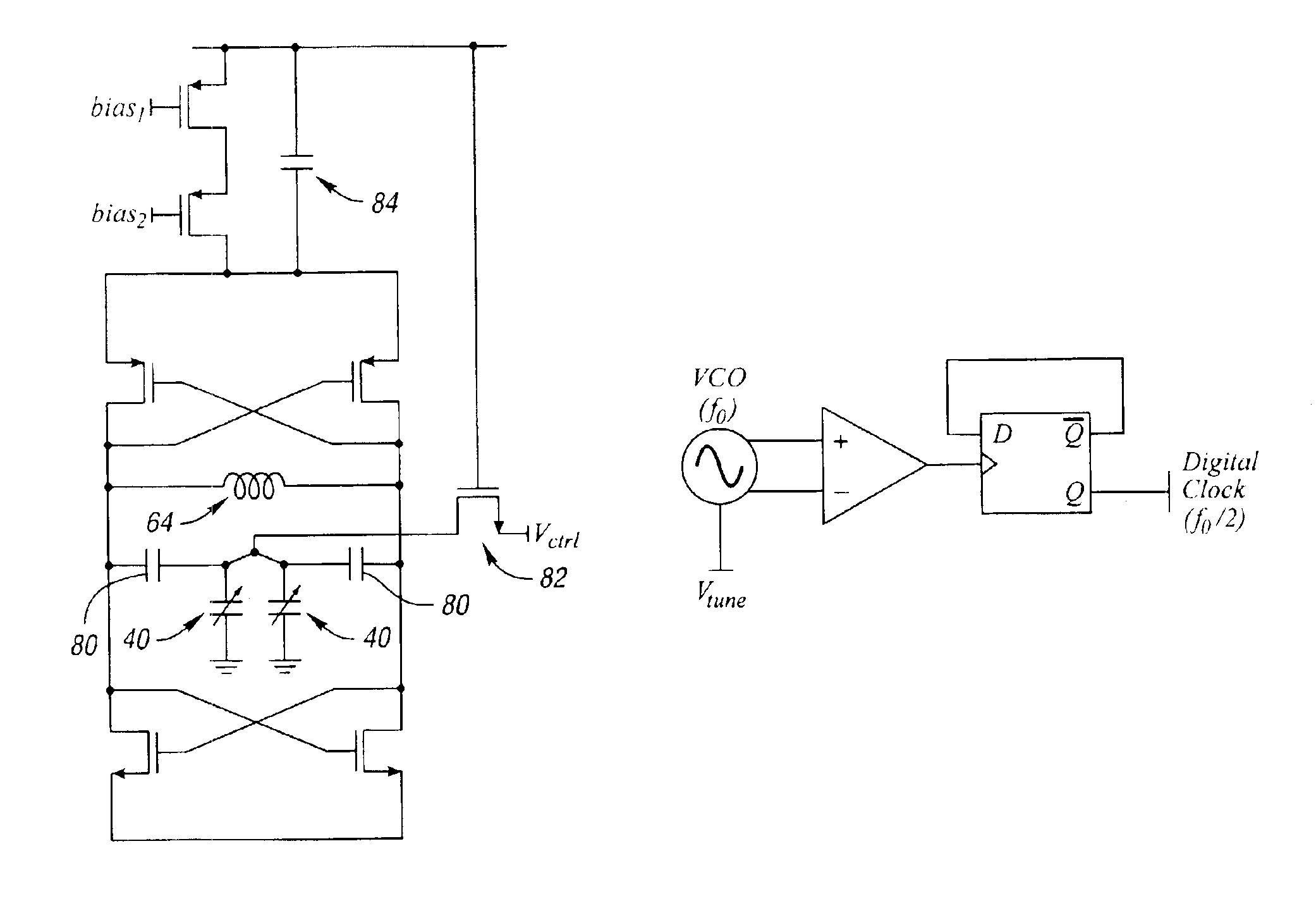
[0170]FIG. 7c illustrates the present invention. Here the blocking capacitors of the embodiment of FIGS. 7a and 7b are not needed as the tuning voltage for the MEMS varactor (i.e. 52′) is applied to a common node that is isolated from the sustaining circuit by the MEMS varactor structures themselves. The oscillator includes an inductor 72′ and a common mode capacitor 87′. As indicated by the prime designation, the varactors 52′, the inductor 72′ and the capacitor 87′ have the same or similar structure as the varactors 52, the inductor 72 and the capacitor 87 of FIG. 7b.

[0171]The oscillator core of FIG. 8a generates a differential sinusoidal signal, which is tapped across the tank. In order to convert this signal into a clock, or square-wave digital signal, the differential signal is converted to a single-ended signal, as shown in FIG. 8a. This signal then clocks a D-flip-flop that has its complementary output tied back to the D input. From here, the clock can be divided arbitrarily...


PUM


Abstract

MEMS-based, computer system, clock generation and oscillator circuits and LC-tank apparatus for use therein are provided and which are fabricated using a CMOS-compatible process. A micromachined inductor (L) and a pair of varactors (C) are developed in metal layers on a silicon substrate to realize the high quality factor LC-tank apparatus. This micromachined LC-tank apparatus is incorporated with CMOS transistor circuitry in order to realize a digital, tunable, low phase jitter, and low power clock, or time base, for synchronous integrated circuits. The synthesized clock signal can be divided down with digital circuitry from several GHz to tens of MHz—a systemic approach that substantially improves stability as compared to the state of the art. Advanced circuit design techniques have been utilized to minimize power consumption and mitigate transistor flicker noise upconversion, thus enhancing clock stability.

Description

CROSS-REFERENCE TO RELATED APPLICATION[0001]This application claims the benefit of U.S. provisional application Ser. No. 60 / 360,314, filed Feb. 26, 2002 and entitled “Low-Phase Noise, Low Power, Monolithic, MEMS-Based Voltage Controlled Oscillator in Silicon-On-Insulator Technology.”BACKGROUND OF THE INVENTION[0002]1. Field of the Invention[0003]This invention relates to MEMS-based, computer systems, clock generation and oscillator circuits and LC-tank apparatus for use therein.[0004]2. Background Art[0005]Oscillators serve a variety of purposes in electronic systems and integrated circuits. For example, in RF systems, oscillators are typically used for frequency translation, via mixing, to and from low and high frequencies, or the baseband and passband, respectively. In mixed-signal circuits, such as switched capacitor circuits, a clock is required to open and close the switches within specific intervals. In microcontrollers, oscillators set the time base, or clock, of the system, ...

Claims


Application Information

Patent Timeline
IPC IPC(8): H03K21/00H01F17/00H01L23/522H03B5/02H03B5/12H03B5/18H03B5/32H03H7/01H03K12/00
CPCH01F17/0006H01L23/5227H03B5/18H03B5/32H03H7/0115H01G5/40H03B5/1228H03B5/1212H03B5/124H01L2924/3011H03H2007/006H01L2924/0002H01L2924/00H03H3/00H03H9/00
Inventor MCCORQUODALE, MICHAEL S.BROWN, RICHARD B.
Owner RGT UNIV OF MICHIGAN
Why Eureka
Try Eureka