Smoothing agents to enhance nucleation density in thin film chemical vapor deposition

a thin film chemical vapor deposition and nucleation density technology, applied in chemical vapor deposition coatings, metal material coating processes, coatings, etc., can solve the problems of reducing the overall device performance, reducing the uniformity of the device, and achieving the desired reduction of device dimensions, etc., to achieve enhanced nucleation densities, low surface roughness, and high degree of smoothness

Active Publication Date: 2014-09-30
THE BOARD OF TRUSTEES OF THE UNIV OF ILLINOIS
View PDF10 Cites 8 Cited by
  • Summary
  • Abstract
  • Description
  • Claims
  • Application Information

AI Technical Summary

Benefits of technology

[0017]The present invention augments methods for making structures, including nanosized and microsized thin film structures that exhibit a high degree of smoothness useful for applications in microelectronics. Deposition processes of the invention utilize smoothing agents capable of selectively adjusting the relative rates of processes involved in thin film formation and growth to access enhanced nucleation densities resulting in smooth thin film structures, including ultrathin (e.g., <10 nm) smooth films. The invention provides methods for conformally coating and / or filling features of a substrate with a film, including high aspect ratio (e.g. aspect ratio>10) recessed features such as trench and / or via structures having nanosized vertical (e.g. depth) and / or lateral (e.g., width and length) dimensions. In an embodiment, for example, the present methods are useful for making thin films having a low surface roughness such as a root mean squared (rms) surface roughness less than or equal to 1 nm. In an embodiment, for example, the present methods enable formation of smooth thin film structures exhibiting substantially uniform densities (e.g., within 20%) that are substantially free of pinholes or other gaps (e.g., having a volume of void per area of film less than or equal to 1×10⁻⁶ μm3 / μm2, or 1×10⁻⁶ μm) in the bulk or interface of the thin film and a device substrate. The present methods are compatible with a wide range of existing materials, processing techniques and processing conditions, and, thus, provide a versatile processing platform for making diverse classes of device structures, including diffusion barriers, dielectric layers and metallic layers, such as electrical contacts and interconnects. Methods of the present invention are useful for fabricating a range of functional electronic devices including integrated electronic circuits, macroelectronic devices and arrays, memory devices, display devices, sensors, MEMS & NEMS systems, photovoltaic devices, and micro- and nanofluidic systems.
[0022]In aspect, the smoothing agent is an inhibitor gas. In an embodiment, for example, accommodation of the smoothing agent by the nuclei, the substrate or both the nuclei and the substrate decreases the growth rate of the nuclei sufficiently such that growth and coalescence of nuclei, including additional nuclei, on the substrate generates the smooth layer. In an embodiment, for example, accommodation of the smoothing agent by the nuclei, the substrate or both the nuclei and the substrate decreases the growth rate of the nuclei by a factor of at least 2 relative to a growth rate of the nuclei in the absence of the smoothing agent. In an embodiment, for example, accommodation of the smoothing agent by the nuclei, the substrate or both the nuclei and the substrate decreases the growth rate of the nuclei by a factor selected over the range of 2 to 100 relative to a growth rate of the nuclei in the absence of the smoothing agent. In an embodiment, for example, the precursor gas has a net sticking coefficient with respect to accommodation on the nuclei, wherein accommodation of the smoothing agent by the nuclei, the substrate or both the nuclei and the substrate results in a decrease of the net sticking coefficient of the precursor gas with respect to accommodation on the nuclei by a factor greater than or equal to 2. In an embodiment, for example, the precursor gas has a net sticking coefficient with respect to accommodation on the nuclei, wherein accommodation of the smoothing agent by the nuclei, the substrate or both the nuclei and the substrate results in a decrease of the net sticking coefficient of the precursor gas with respect to accommodation on the nuclei by a factor selected from the range of 2 to 1000, and optionally selected from the range of 2 to 100, and optionally selected from the range of 2 to 10.
[0024]An advantage of the present methods is the ability to generate high quality smooth and ultrathin film structures, for example, thin films having thicknesses less than or equal to 100 nanometers, optionally less than or equal to 20 nanometers, optionally less than 10 nanometers, and optionally less than 5 nanometers. In an embodiment, for example, the ultrathin smooth layer generated by the present methods has a thickness selected over the range of 0.3 nm to 20 nm. An advantage of the present methods is the ability to generate high quality ultrasmooth film structures, for example, having a surface roughness (rms) less than or equal to 20 nm, optionally a surface roughness (rms) less than or equal to 10 nm, and optionally a surface roughness (rms) less than or equal to 5 nm. In an embodiment, for example, the smooth layer generated by the present methods has a surface roughness (rms) selected over the range of 0.1 nm to 10 nm, and optionally a surface roughness (rms) selected over the range of 0.1 nm to 2 nm.
[0025]Use of a smoothing agent comprising an inhibitor gas is beneficial in some methods of the present invention for selectively adjusting the relative rates of processes involved in the nucleation, growth and coalescence of deposited materials, such as chemical vapor deposition and atomic layer deposition materials. In some aspects, for example, processing using an inhibitor gas provides control over the relative rates of formation and growth of nuclei on a substrate surface so as to access deposition conditions resulting in the formation of a smooth conformal layer, such as a smooth conformal thin film.
[0027]In some embodiments, for example, smoothing agent is accommodated by surfaces of the growing nuclei, thereby generating condensed phase species on, or within, the nuclei that decrease the rate of growth of the nuclei, for example, by decreasing the rate of accommodation of precursor gases by surfaces of the nuclei. In some embodiments, for example, interaction between the smoothing agent and the surfaces of the nuclei results in formation of condensed phase species on the surface and / or within the nuclei, such as species physisorbed on the surface of the nuclei, species chemisorbed on the surface of the nuclei and species on the surface of the nuclei that are products of reaction(s) of the smoothing agent and nuclei and / or decomposition of the smoothing agent. Such condensed phase species include condensed phase inhibitor species including stable species present on the surface of the nuclei and metastable species that undergo reaction and / or subsequent release to the gas phase. In some embodiments, processes of accommodation of the smoothing agent by the surfaces of the nuclei and loss of condensed phase species from the surfaces of the nuclei establish a steady state amount of condensed phase species on the nuclei, for example, a steady state amount of condensed phase species providing a decrease in the of rate of growth of nuclei relative to the rate of generation of new nuclei so as to generate a smooth layer on the substrate. In some embodiments, the presence of condensed phase species on the surface and / or in the bulk of nuclei function to increase the rates of chemical reactions resulting in reformation and subsequent desorption of precursor.
[0041]In an aspect, the invention provides a method of enhancing a nucleation density of a thin film deposited on a substrate, the method comprising the steps of: (1) providing the substrate having a receiving surface; (2) contacting the receiving surface of the substrate with a precursor gas, wherein accommodation of the precursor gas by the substrate results in formation of nuclei of deposited material on the receiving surface of the substrate; (3) contacting the nuclei on the receiving surface with the precursor gas; wherein accommodation of the precursor gas by the nuclei, substrate or both the nuclei and the substrate results in growth of the nuclei at a growth rate; and (4) contacting the nuclei, the substrate or both the nuclei and the substrate with a smoothing agent, wherein accommodation of the smoothing agent by the nuclei, the substrate or both the nuclei and the substrate results in enhancement of the nucleation density of the thin film deposited on the substrate. In an embodiment, for example, the nucleation density of the thin film is greater than or equal to 1×1011 cm−2. In an embodiment, for example, the thin film coalesces at a thickness less than or equal to 5 nm and optionally less than or equal to 1 nm and optionally less than or equal to 0.5 nm. In an aspect, the nucleation density of the thin film is enhanced relative to equivalent deposition conditions but in the absence of smoothing agent, for example, enhanced by a factor of at least 2 and optionally enhanced by a factor of at least 100.

Problems solved by technology
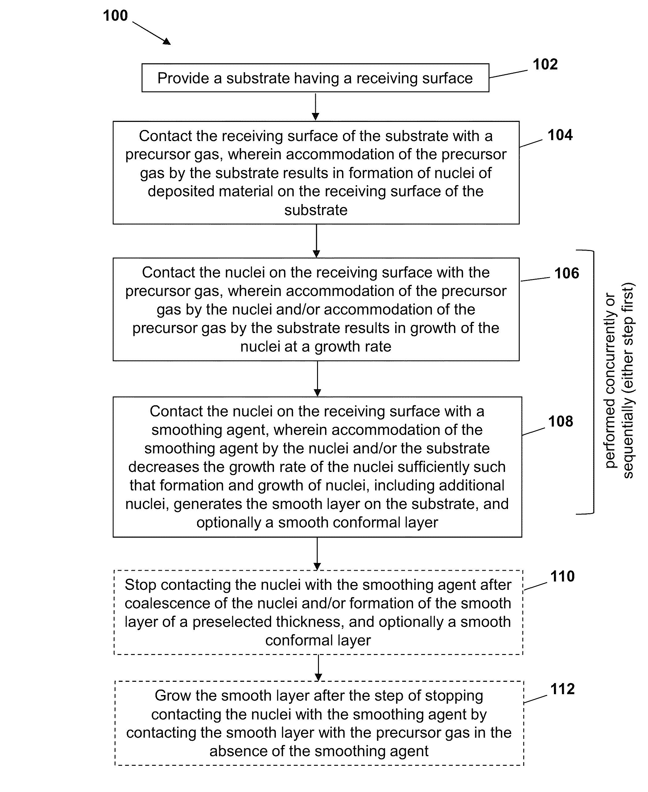
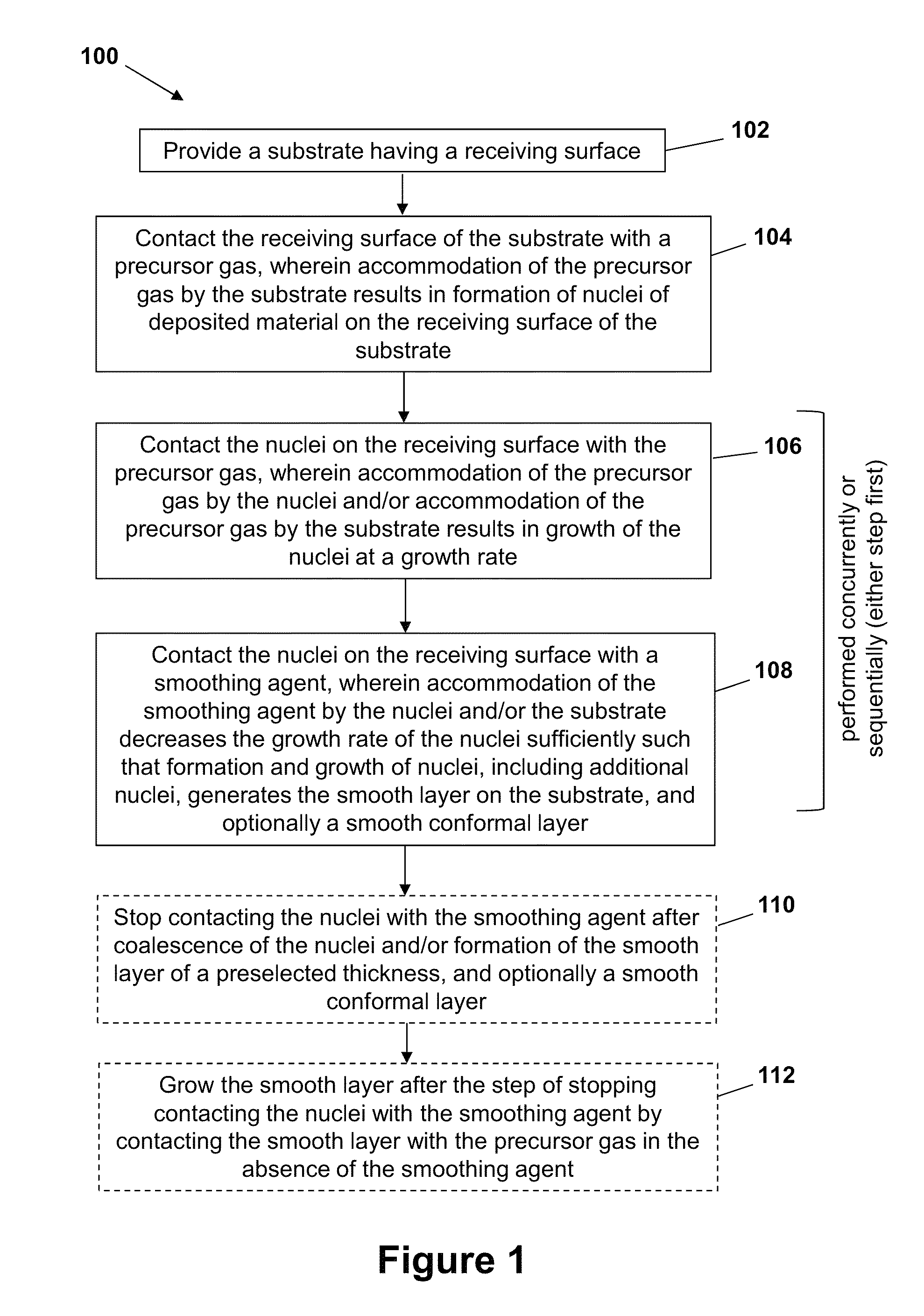
As target device dimensions continue to be reduced with the evolution of advanced lithography techniques, significant technical challenges are presented for conformally filling or coating such high aspect ratio nanometer and micron sized structures with functional materials.
These challenges constitute a barrier to achieving the desired reduction of device dimensions in ultra-large scale integrated circuit (ULSI) architecture and the multilevel metallization therein.
Voids and gaps, such as pinholes, are undesirable because they affect the electronic and chemical properties of the deposited layer, such as inductance, resistivity and / or capacitance, thereby, potentially degrading overall device performance and undermining device uniformity.
Further, voids and gaps in the bulk of the deposit or between the deposit and surfaces of the recessed feature also compromise overall mechanical integrity of the processed structure and may give rise to device failure.
As an example, there is currently a need for processing techniques for making thin diffusion barriers without any pinholes or other gaps, as such device structures may fail if there is even a single pinhole allowing incompatible materials to penetrate—such as Cu in dielectric layers.
While at least in part addressing some of the problems with processing high aspect ratio features, these techniques are not compatible with all types of deposition materials, substrates and recessed feature geometries.
In addition, each technique presents its own set of limitations that impedes adoption and implementation.
Due to the near-unity net sticking coefficient of the arriving flux in most PVD coating applications, the ability of PVD processes to coat high aspect ratio features uniformly is severely limited.
Modified PVD processes, however, such as collimated sputtering and ionized PVD have been demonstrated to provide some limited success in coating and filling moderate aspect ratio (≦5:1) features.
Film and substrate damage from high energy ions, however, can be a severe limitation in this process.
Disadvantages of these techniques include the need for intermediate photolithographic steps to define a mask layer, and the need for mechanical polishing to remove unwanted seed layer.
The time limit stems from the fact that the suppressor is re-emitted from the film surface at some rate and ultimately will diffuse to the bottom of the trench, despite the fact that it has a higher net sticking coefficient and lower concentration with respect to the precursor.
A significant disadvantage of the time domain techniques described in Heitzinger et al. is that coating / filling larger structures requires a longer time to build up the appropriate layer thickness; and, thus, the time-limit bottom-up growth will not work because the suppressor will reach the, bottom of the via before the structure is filled.
Moreover, the time delay in these systems is very short (e.g. 54.25 s in FIGS. 8 and 23.92 s in FIG. 9 of Heitzinger et al.) and it is difficult to control such a short growth time during processing.

Method used


Image

  • Smoothing agents to enhance nucleation density in thin film chemical vapor deposition
  • Smoothing agents to enhance nucleation density in thin film chemical vapor deposition
  • Smoothing agents to enhance nucleation density in thin film chemical vapor deposition

Examples


example 1

Low Temperature Chemical Vapor Deposition of Hafnium Nitride-Boron Nitride Nanocomposite Films

[0105]Nanocomposite HfNx—BN thin films are deposited by chemical vapor deposition at substrate temperatures of 350-800° C. using the precursor hafnium borohydride, Hf(BH4)4, in combination with ammonia, NH3. Below 350° C., the product is metallic HfB2 with essentially no incorporation of nitrogen. However, the presence of ammonia decreases the HfB2 deposition rate considerably; this growth suppression effect is attributed to blocking of reactive surface sites by adsorbed ammonia molecules. At substrate temperatures above 350° C., film deposition occurs; however, the HfB2 phase is completely absent. The resulting film stoichiometry is HfByN2.5; although the value of y is difficult to determine precisely, it is about unity. X-ray photoelectron spectroscopy (XPS) analysis detects Hf—N and B—N bonds but no Hf—B bonds; thus the films are nanocomposites that consist of a mixture of hafnium nitrid...

example 2

Growth Inhibitors to Enhance Nucleation Density in Thin Film Chemical Vapor Deposition

[0159]Many nanotechnologies, especially those involved in the fabrication of integrated circuits, require low temperature deposition of extremely thin, pinhole-free and ultra-smooth films that are conformal on high aspect ratio features such as trenches and vias [1]. Growth processes in which the reaction rate of the precursor species can be limited to very small values, such as chemical vapor deposition (CVD) or atomic layer deposition (ALD), can meet the requirement for conformality [2-6]. However, poor nucleation, especially on dielectric substrates, seriously degrades the morphology [7,8]: if the areal density of nuclei is low, then the initial film growth takes place in an island mode and the film does not fully coalesce until its thickness is much larger than acceptable for the device design. In addition, the coalescence of large islands produces a large initial surface roughness and the inte...

example 3

Nucleation and Growth of Cu Films Using Smoothing Agents

[0196]Nucleation and growth of thin Cu films on copper oxide substrates (e.g., CuO / CuO2) is examined using a Cu(hfac)vtms or Cu(hfac)MHY precursor in the presence and absence of a smoothing agent comprising vtms or MHY. These results are compared to experiments corresponding to growth of smooth HfB2 layers using Hf(BH4)4 precursor gas and an NH3 smoothing agent.

[0197]FIG. 14 provides AFM images of a HfB2 film fabricated according to exemplary methods of the present invention at three positions of a recessed feature (250 micron width, 1.5×10⁴ micron depth) of a SiO2 substrate: (a) at the opening of a trench, (b) at the midpoint of an interior sidewall of the trench, and (c) at the bottom of the trench. The results in FIG. 14 demonstrate that the present methods provide substantially uniform nucleation along a recessed feature having aspect ratio of 60:1. Still referring to FIG. 14, the conditions employed are a macro trench: 250...


PUM

PropertyMeasurementUnit
surface roughnessaaaaaaaaaa
thicknessaaaaaaaaaa

Abstract

The present invention provides methods for making structures, including nanosized and microsized thin film structures that exhibit a high degree of smoothness useful for applications in microelectronics. Deposition processing of the invention utilize smoothing agents capable of selectively adjusting the relative rates of processes involved in thin film formation and growth to access enhanced nucleation densities resulting in smooth thin film structures, including ultrathin (e.g., <10 nm) smooth films.

Description

CROSS-REFERENCE TO RELATED APPLICATIONS[0001]This application claims the benefit of priority from U.S. Provisional Patent Application No. 61 / 408,777, filed Nov. 1, 2010, which is hereby incorporated by reference in its entirety.STATEMENT REGARDING FEDERALLY SPONSORED RESEARCH OR DEVELOPMENT[0002]This invention was made, at least in part, with United States governmental support awarded by National Science Foundation Grant NSF CH 07-50422. The United States Government has certain rights in this invention.BACKGROUND OF THE INVENTION[0003]Substrate processing combining advanced lithographic processing and thin film deposition techniques enables fabrication and integration of device structures having dimensions ranging from 10s of nanometers to 10s of centimeters. Such state of the art material processing methods are generally compatible with a range of substrate and deposition materials, including high quality dielectric, semiconducting, conducting and biological materials. Given the de...

Claims


Application Information

Patent Timeline
Patent Type & Authority Patents(United States)
IPC IPC(8): C23C16/00C23C16/02C23C16/04C23C16/18
CPCC23C16/0272C23C16/04C23C16/18
Inventor ABELSON, JOHN R.GIROLAMI, GREGORY S.BABAR, SHAISTAKUMAR, NAVNEET
Owner THE BOARD OF TRUSTEES OF THE UNIV OF ILLINOIS
Why Eureka
Try Eureka