

Ion beam process for deposition of highly abrasion-resistant coatings
a coating and ion beam technology, applied in the field of coating deposition, can solve the problems of subject to abrasion, and poor abrasion resistance of coating lenses, and achieve the effect of low friction coefficient and high hardness
- Summary
- Abstract
- Description
- Claims
- Application Information
AI Technical Summary
Benefits of technology
Problems solved by technology
Method used
Image

Examples
example a
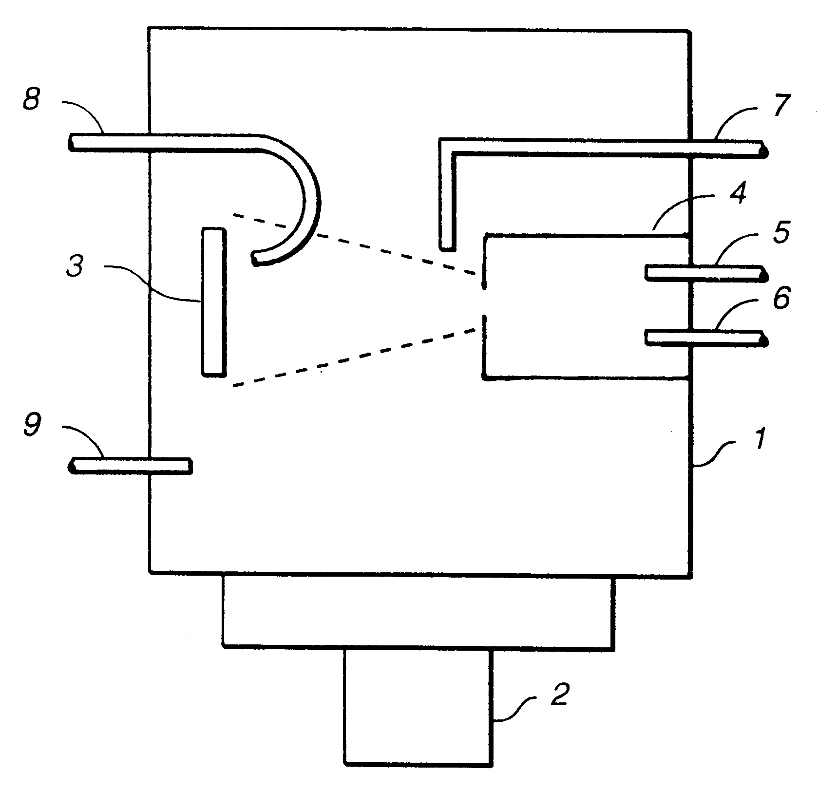
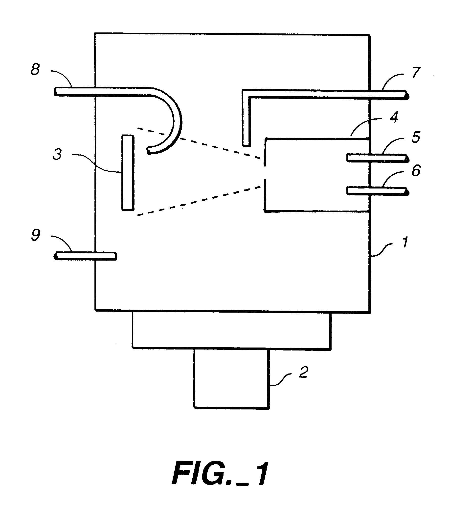
A three inch diameter Si(001) wafer and a 1".times.1" piece of fused silica were cleaned in isopropyl alcohol, dried with nitrogen gas and mounted onto a graphite disk using Kapton tape. The graphite plate was mounted into a stainless steel vacuum chamber pumped by a 10" diffusion pump and the chamber was evacuated to a pressure of 9.2.times.10.sup.-6 Torr. The substrates were sputter-etched for one minute by an argon ion beam generated from an End Hall ion source (manufactured by Commonwealth Scientific as Mark II) operated on 5 sccm of argon, at an anode potential of 171 volts, and an anode current of 1.08 amps. The Ar gas was introduced directly into the plasma chamber of the ion source. The pressure in the chamber was 7.4.times.10.sup.-5 Torr. A hot filament was used as the electron source. After sputter-etching methane gas was introduced directly into the plasma chamber of the ion source at a flow of 10 sccm resulting in a pressure of 6.6.times.10.sup.-5 Torr. The anode voltage...
example b
A three inch diameter Si(001) wafer and a 1".times.1" piece of fused silica were cleaned in isopropyl alcohol, dried with nitrogen gas and mounted onto a graphite disk using Kapton tape. The graphite plate was mounted into a stainless steel vacuum chamber pumped by a 10" diffusion pump and the chamber was evacuated to a pressure of 2.3.times.10.sup.-6 Torr. The substrates were sputter-etched for two minutes by an argon ion beam generated from the End Hall ion source (Commonwealth Scientific's Mark II) operated on 5 sccm of argon, at an anode potential of 170 volts and an anode current of 1.25 amps. The argon gas was introduced directly into the plasma chamber of the ion source. The pressure in the chamber was 4.8.times.10.sup.-5 Torr. A hot filament was used as the electron source. After sputter-etching, the argon was shut off and cyclohexane gas was introduced directly into the plasma chamber of the ion source resulting in a chamber pressure of 1.4.times.10.sup.-4 Torr. The anode v...
example c
A three inch diameter Si(001) wafer and a 1".times.1" piece of fused silica were cleaned in isopropyl alcohol, dried with nitrogen gas and mounted onto a graphite disk using Kapton tape. The graphite plate was mounted into a stainless steel vacuum chamber pumped by a 10" diffusion pump and the chamber was evacuated to a pressure of 2.5.times.10.sup.-6 Torr. The substrates were sputter-etched for two minutes by an argon ion beam generated from the End Hall ion source (Commonwealth Scientific's Mark II) operated on 6.4 sccm of argon, at an anode potential of 160 volts and an anode current of 0.98 amp. The Ar gas was introduced directly into the plasma chamber of the ion source. The pressure in the chamber was 2.1.times.10.sup.-4 Torr. A hot filament was used as the electron source. After the sputter-etching was complete, tetramethylcyclotetrasiloxane was introduced into the plasma chamber of the ion source and the argon was turned off resulting in a chamber pressure of 6.7.times.10.su...
PUM
| Property | Measurement | Unit |
|---|---|---|
| Fraction | aaaaa | aaaaa |
| Thickness | aaaaa | aaaaa |
| Pressure | aaaaa | aaaaa |
Abstract
Description
Claims
Application Information