
High temperature gas seals

Active Publication Date: 2004-07-15
VERSA POWER SYST
View PDF8 Cites 42 Cited by
  • Summary
  • Abstract
  • Description
  • Claims
  • Application Information

AI Technical Summary

Benefits of technology

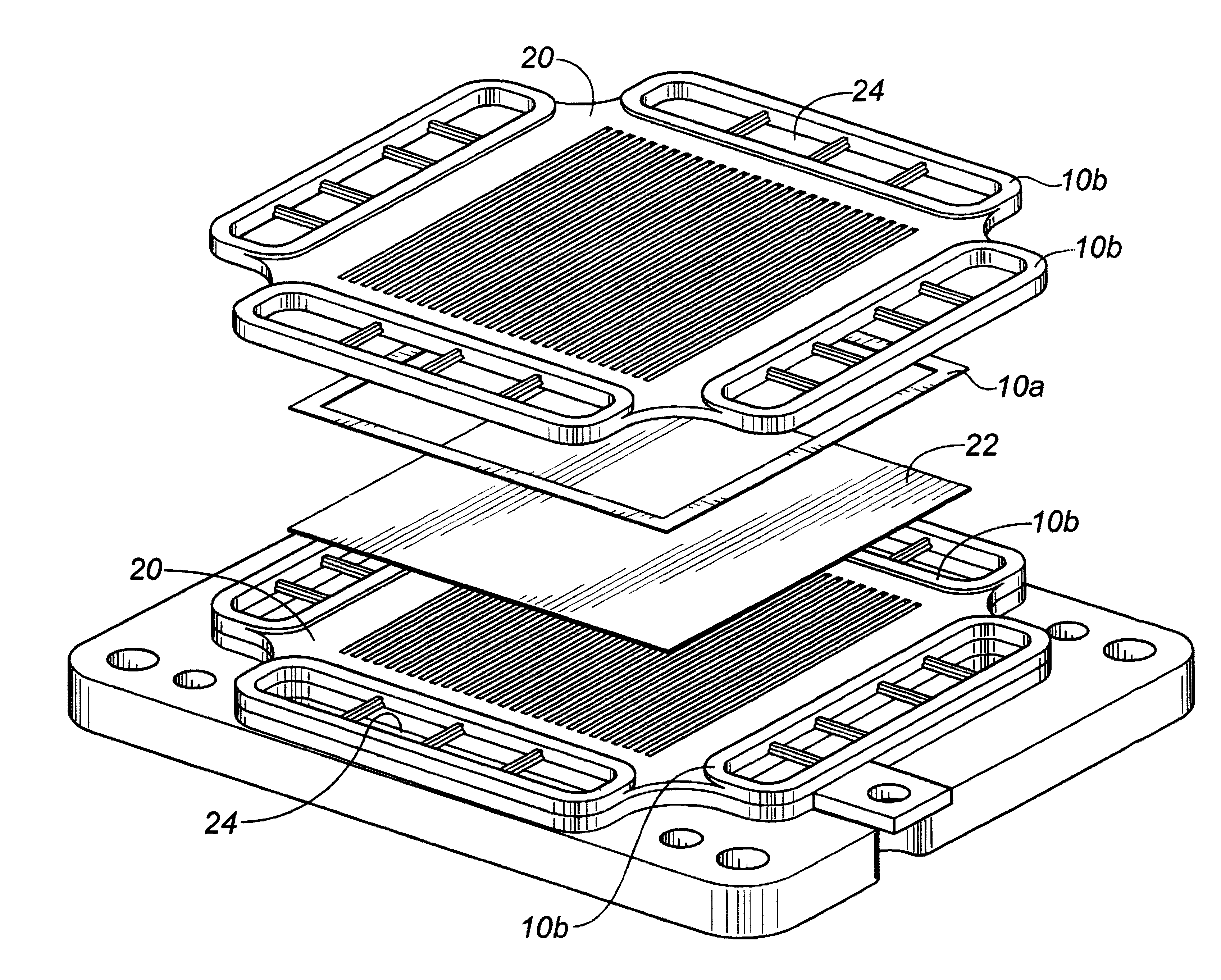
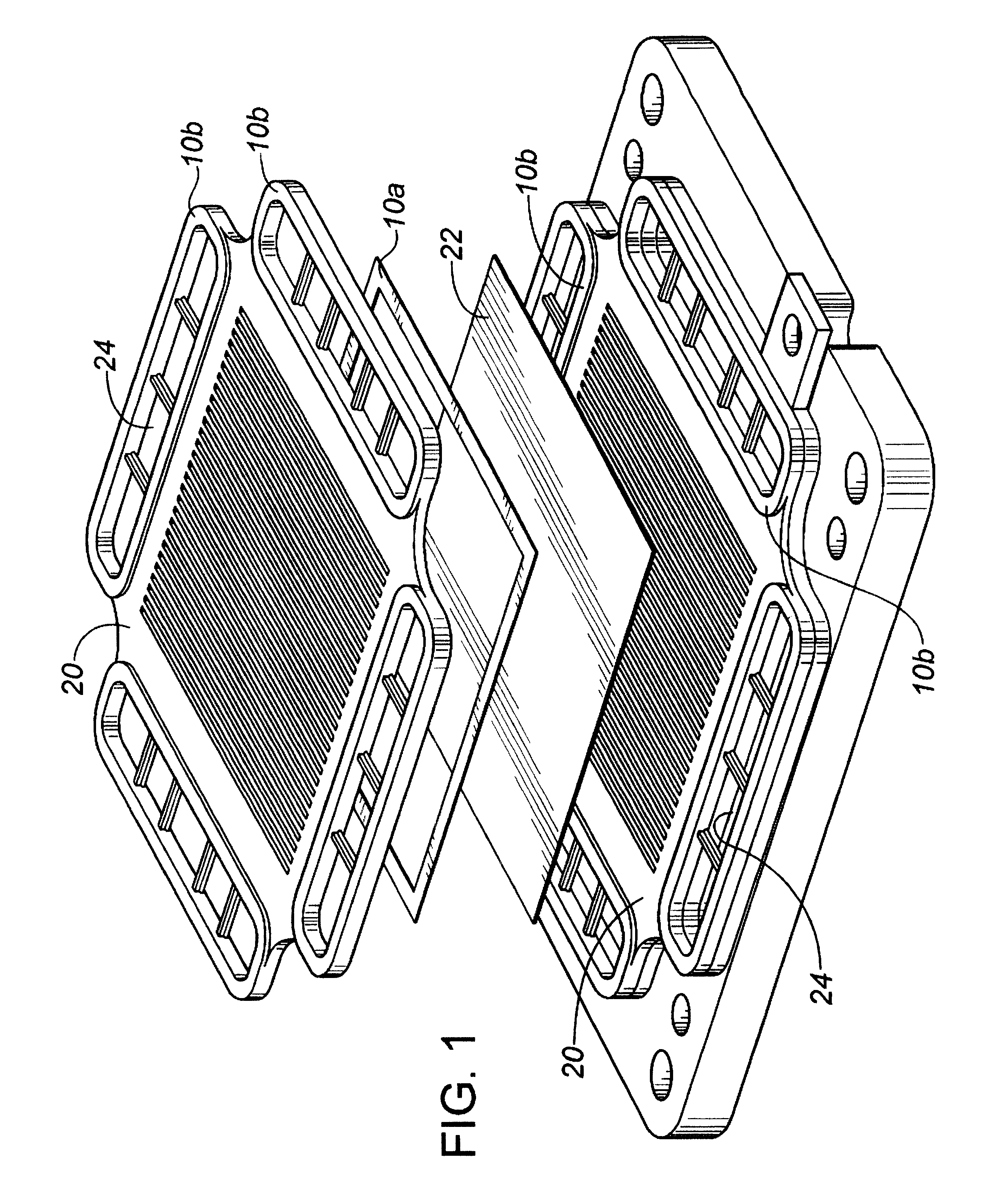
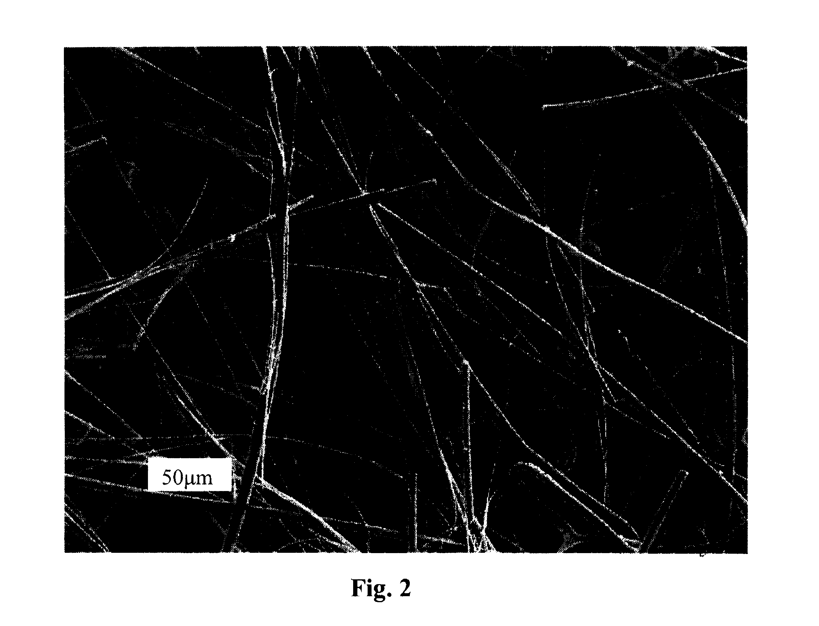
[0029] When the seal is compressed in the fuel cell stack, the particles block the potential leakage paths or create a very torturous leak path for the gases, providing a non-hermetic but effective seal. The fibres act as a physical restraint to the ceramic powder, allowing the shape to be formed and maintained throughout its service life. The ceramic powder is packed into the alumina matrix, but is not sintered into a contiguous member and remains unsintered at the operating temperatures of the fuel cell, which may be typically in the range of 500.degree. C. to 1000.degree. C. Because the ceramic components of the seal are not sintered, the seal may flex or experience thermal expansion or contraction without breaking down. As well, non-adhesive installation allows for easy assembly and disassembly, allowing for component reuse, and for increased resistance of the seal to vibrations, permitting use in a wider variety of applications, such as automotive.
[0031] In the present invention, it is the combination of the particles within the fibre matrix which provides adequate sealing performance. Any suitable process may be used to load the powder into the fibre matrix. In one embodiment, the seal may be formed by first making an alumina felt from alumina fibres and then forming and rolling into a sheet to a desired thickness. The felt may then be soaked in a suspension of ceramic powder in a liquid media such as an alcohol, in a process referred to herein as dip impregnation. The liquid media may be any liquid but preferably should have low surface tension and be relatively volatile to allow quick evaporation. Alcohols such as ethanol and isopropanol are effective liquid media for this purpose. The ceramic powder is drawn into the matrix of the felt by the capillary action of the felt, and thus creating a reasonably dense sealing media. After absorption of the ceramic powder, the felt is dried to remove the ethanol and the felt is cut or punched to the required size and shape of seal desired. The seal may then be pre-compressed prior to installation or it may be pre-compressed prior to cutting or punching.
[0036] In one embodiment of the present invention, a slurry of fibres and powders may be tape cast to form a flexible seal with an overall density that is significantly greater than that of seals described by the prior art. The purpose of the fibre is to give certain strength and flexibility to the seal after binder burnout. In the case of using alumina as structural material the powder packing density may be about 2.6 g / cm.sup.3 in a green tape and about 2.3 g / cm.sup.3 fired tape-cast seal. A density of 2.3 g / cm.sup.3 is equivalent to a porosity of less than 43%. We have found that maintaining relatively large particle sizes in the powder allows relatively good compressibility, flexibility, and high powder loading density. In one embodiment, for example, 60% of the particles are about 5 .mu.m in diameter and the remainder may be about 1 .mu.m in diameter.
[0045] Unused tape seals may be recycled by re-dissolving the seal in a solvent and recasting the resulting slurry in the same manner as the original seal was tape cast. The ability to recycle unused tape cast seals may significantly improve the economics of seal production using this method.

Problems solved by technology

However, the softening point of glass limits the maximum operating temperature.
If not, high thermal stresses can develop within the components during stack heat-up and / or cool-down, causing fracture of the cell or seal.
Unfortunately, these glasses typically display signs of devitrification within the first few hours of exposure at operating temperature.
As the glass begins to crystallize, its carefully engineered thermal expansion properties change significantly, ultimately limiting the number of thermal cycles and the rate of cycling at which the resulting joint is capable of surviving.
Even if the coefficients of thermal expansion are matched, non-uniform thermal expansion can still result, as the thermal conductivities of the stack components are typically not matched.
As glass is an inherently brittle material, it cracks and fails under thermal cycling conditions, and as a result of jarring shocks or vibrations, which is often the case in mobile applications.
A further disadvantage of glass seals is that they can have a chemical incompatibity with electrocatalytic cells, leading to performance degradation during operation.
SOFCs are particularly sensitive to alkali elements contained in many glass seals, which have been found to detrimentally affect the SOFC catalyst.
Glass composition and phase shifting due to interaction with contact materials is also a problem for long-term service.
However, compliant seals of this nature suffer from the disadvantage of inadequate sealing performance, primarily due to the lack of a reliable high-temperature sealing material that would form the basis of the compliant seal.
A number of materials have been considered, including mica, nickel, and copper, but each has been found deficient for any number of reasons, ranging from oxidation resistance in the case of the metals to poor hermeticity and through-seal leakage with respect to the mica.
In the case of mica, while being able to withstand high temperatures, the natural variance in thickness of mica sheets and the relative non-compressibility of the mica both contribute to this poor sealing behavior.
Additionally, it has been found that the mica may leach minerals that can poison the catalyst in the cell.

Method used


Image

  • High temperature gas seals
  • High temperature gas seals
  • High temperature gas seals

Examples


example 1

Preparation of Dip Impregnated Seal and Room Temperature Leakrate Testing

[0047] Zircar.TM.0.040"Al.sub.2O.sub.3 fiber felt was cut out into seal size 10.times.10 cm. The cut pieces of Zircar were then placed on a small square of Mylar.TM.(about 15 cm.times.15 cm) and immersed in either (A) 8 vol % zirconia or (B) 10 vol % Al.sub.2O.sub.3 suspension solutionbath for 15 seconds using light agitation. The Mylar.TM. was then lifted and tilted in a circular motion to distribute the remaining solution and to allow any excess solution to drip off. The seal was allowed to dry on the Mylar.TM. sheet for approximately 90 minutes. Once dried the weight, Wd, was recorded and some of the seals were dipped 2 or 3 times with weight recorded after each dipping.

[0048] Leak rate was measured at room temperature with air as test gas, the test device is composed of two polished steel plates, hydraulic pressure supplier, pressure sensor, air pressure adjustor and gauge, and leak rate flow-meters. The th...

example 2

Tape Cast Seal Formulations

[0053]

2TABLE 2 Tape Cast Seal Formulations Trial Fibre Fibre Powder # Type Wt % Wt % Solvent Plasticizer 1 Saffil HA 15 85 MEK / EtOH PEG / DBP 2 Saffil HA 20 80 MEK / EtOh PEG / DBP 3 Saffil HA 20 80 MEK / EtOH PEG / DBP 4 Saffil RF 20 80 MTBK / Toluene / Santicizer 160 .TM. EtOH

[0054] Tape cast seals were formed by mixing alumina fibres with alumina powder in either 15:85 or 20:80 weight proportion, on a ceramic basis. A tape-casting slurry was formed using either methyl ethyl ketone (MEK) (66.6 wt %) and absolute anhydrous ethanol (33.3 wt %) as the solvent system or a mixture of MIBK, toluene and anhydrous ethanol. The MEK / EtOH formulations use polyethylene glycol 400 (PEG) and dibutyl phthalate (DBP) as the plasticizer, while the MIBK solvent system utilized Santicizer 160.TM. (benzyl butyl phthalate). Either Butvar.RTM. B76 or B79, or mixtures of both, were used as polyvinyl butyral (PVB) binders, which include small amounts of polyvinyl alcohol and polyvinyl aceta...

example 4

Density, Shrinkage and Leakrate Testing

[0058] Density and shrinkage data were collected for each tape. Four 1 square inch pieces were cut and measured for density. Two of these pieces were then fired at 750 deg. C. for 1 hour to burn out the organics. These same pieces were then re-measured to determine their post firing density and shrinkage values. Table 4 is a summary of this data.

4TABLE 4 Density and Shrinkage Summary Average Green Fired Green Fired Green Average Average Trial Density Density Porosity Porosity Thickness Shrinkage Shrinkage Leakrate # (g / cm.sup.3) (g / cm.sup.3) (%) (%) (mm) X - Y (%) Z (%) (ml / min / in)* 1 2.78 2.51 29.9 36.7 0.515 -0.05 -1.17 0.03 2 2.18 2.03 45.1 48.9 0.875 -0.06 -0.69 0.05 3 2.86 2.54 28.0 36.0 0.455 -0.04 0.10 0.03 4 2.53 2.29 36.4 42.3 0.519 0.29 -0.10 0.03 *Leakrates were tested at a 50 psi compressive force, 750.degree. C., 0.5 psi air. The test device detection limit was 0.03 ml / min / inch.


PUM

PropertyMeasurementUnit
Porosityaaaaaaaaaa
Porosityaaaaaaaaaa
Porosityaaaaaaaaaa

Abstract

A flexible seal for use in a solid oxide fuel cell stack is formed from a fibre matrix with a plurality of solid particles through tape casting method. The fibres and particles are preferably ceramic and may be formed from alumina or zirconia. The seal may be formed by forming a slurry of fibres, particles, a binder and a non-aqueous solvent, tape casting the slurry, drying the tape seal, die-cutting, prior to installation in the fuel cell stack.

Description

[0001] The present invention claims the priority of U.S. Provisional Patent Application No. 60 / 319,811 filed on Dec. 24, 2002, the contents of which are incorporated herein by reference.BACKGROUND OF INVENTION[0002] The present invention relates to high temperature gas seals, particularly for use in a planar solid oxide fuel cell stack.[0003] A planar solid oxide fuel cell (pSOFC) stack has three primary constituents: a ceramic electrochemical cell membrane, metallic interconnects, and an arrangement of seals. To perform the function of converting chemical energy into electrical energy, a SOFC membrane must have one electrochemical face exposed to an oxidant gas, and the other exposed to a fuel gas, all at an operating temperature above 500.degree. C. A metallic interconnect (IC) provides fuel and oxidant gas distribution to the cells by means of separate plenums, and when arranged between cells in a stack arrangement, also transfers electrical current from one cell to another. The ...

Claims


Application Information

Patent Timeline
IPC IPC(8): F16J15/02H01M2/08H01M8/02H01M8/24
CPCC04B35/117Y10S428/92C04B35/6264C04B35/803C04B2235/5224C04B2235/6025C04B2235/608C04B2235/616C04B2235/77C04B2235/9615H01M2/08H01M8/0271H01M8/242H01M8/2425Y02E60/522Y02E60/50C04B35/4885H01M8/0282H01M8/0286Y10T428/249964Y10T428/249969Y10T428/249962Y10T428/24997Y10T428/249986C04B35/80H01M8/2483H01M8/2432
Inventor BRULE, ROBERTZHANG, XINGECHAHAL, DHANWANTTANG, ZHENG
Owner VERSA POWER SYST
Learn More