
Method for forming thin film, substrate having thin film formed by the method, and photoelectric conversion device using the substrate

Inactive Publication Date: 2005-06-16
NIPPON SHEET GLASS CO LTD
View PDF7 Cites 18 Cited by
  • Summary
  • Abstract
  • Description
  • Claims
  • Application Information

AI Technical Summary

Benefits of technology

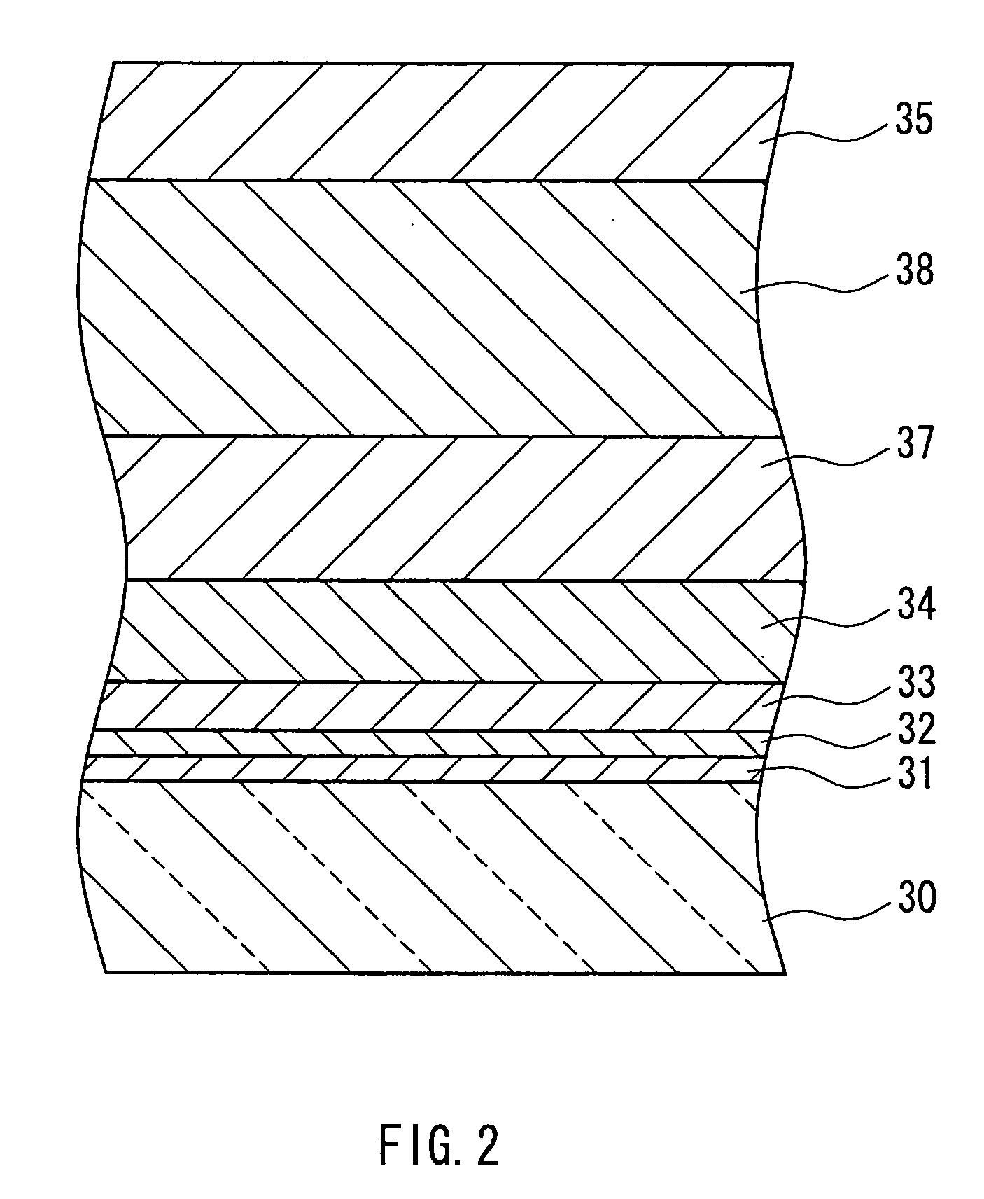
[0024] In particular, when the undercoating film includes two layers, the formation of a thin film containing a metal oxide such as tin oxide or titanium oxide as the main component for the first undercoating layer makes it possible to increase the film deposition rate for the thin film containing a metal oxide as the main component that is directly formed on the second undercoating layer, or to increase the film thickness of the thin film containing a metal oxide as the main component without causing a white turbidity condition. The thin film containing a metal oxide such as tin oxide or titanium oxide as the main component that is used for the first undercoating layer is crystalline, even though it is a very thin film, and a surface roughness originating from crystal grains is formed on the surface thereof. This surface roughness is reflected in the surface of the non-crystalline second undercoating layer, such as silicon oxide or aluminum oxide. For this reason, if the undercoating film is only a non-crystalline undercoating film, such as silicon oxide, the surface becomes completely flat, but since the surface roughness is formed on the surface of the undercoating film, the surface roughness serves to function as starting points for growing the buffer layer or the thin film containing a metal oxide as the main component, exhibiting various similar advantageous effects to those of the above-described buffer layer.
[0025] On the other hand, even if the substrate was glass, the undercoating film is not necessarily required when the substrate is aluminosilicate glass, borosilicate glass, quartz glass, or the like, which does not contain alkaline components. Nevertheless, there are cases in which the undercoating film is necessary for other purposes than preventing an alkaline component from diffusing, and it should not be interpreted as excluding the provision of the undercoating film on a glass that does not contain alkaline components.
[0026] Those glasses that do not contain alkaline components have higher thermal characteristics, such as glass transition temperature, than a soda lime glass, which contains an alkaline component, and therefore, they are capable of forming a thin film containing a metal oxide as the main component at higher temperatures.
[0027] The metal that constitutes the buffer layer may be a different type of metal from the metal of the thin film containing a crystalline metal oxide as the main component, but it is preferable that they are the same type of metal. When they are the same type of metal, crystal growth is induced more in the thin film containing a metal oxide as the main component, and therefore, the fine metallic particles can be made small in particle diameter or less in number, or the content of the metal can be reduced in the buffer layer. For example, when a thin film made of tin oxide or titanium oxide that has a rutile structure is formed as the buffer layer, it is desirable to form a film composed of tin oxide or titanium oxide with the same rutile structure, or a film composed of titanium oxide with an anatase structure, which is very similar to the rutile structure, as the thin film containing a metal oxide as the main component.
[0028] The method for forming the thin film containing a metal oxide as the main component is not particularly limited as long as it is a thermal decomposition method, and examples include a CVD method and a solution-spraying method in which a solution material is sprayed onto a heated substrate. If the buffer layer and the thin film containing a metal oxide as the main component are formed by the same formation method, they can be formed within a short time by a series of manufacturing steps; for this reason, it is preferable that these be formed by the same method in terms of industrial production efficiency. An example is a method in which, after forming the buffer layer using a CVD method, the thin film containing a metal oxide as the main component is successively formed. In this case, however, the formation temperature for the thin film containing a metal oxide as the main component becomes lower than that in the formation of the buffer layer, and therefore, it is desirable to utilize a material with good reactivity, such as a tetrachloride, for the raw material of the thin film containing a metal oxide as the main component.
[0029] Preferable materials for the thin film containing a metal oxide as the main component are chlorides of metals that do not contain organic substances, such as tin dichloride, tin tetrachloride, titanium chloride, zinc chloride, and indium chloride, which are chemically stable and have low environmental load, and tetrachloride of metal is especially suitable to increase the film deposition rate.

Problems solved by technology

Since a glass sheet provided with this thin film reduces the total solar energy transmittance and does not allow the heat within rooms to escape to the outdoors, it is widely available in the market as a low-emissivity glass.
Such methods of forming a thin film containing a metal oxide that utilize thermal decomposition methods are inferior to physical vapor deposition methods, such as a sputtering method, in that it is difficult to obtain a uniform film thickness; nevertheless, they are capable of forming a thin film over a wide area within a short time at a relatively uniform thickness and therefore are suitable for mass production of industrial products.
However, due to high reactivity of tin tetrachloride with water, even when a pipe or the like for the mixed gas was controlled at a temperature of 100° C. to 240° C. as described in JP 9(1997)-40442 A, the pipe was clogged up by the reactant that deposited inside the pipe after only about 3 hour's supplying of a mixed gas of tin tetrachloride and water, making further gas supply impossible.

Method used


Image

  • Method for forming thin film, substrate having thin film formed by the method, and photoelectric conversion device using the substrate
  • Method for forming thin film, substrate having thin film formed by the method, and photoelectric conversion device using the substrate
  • Method for forming thin film, substrate having thin film formed by the method, and photoelectric conversion device using the substrate

Examples


example 1

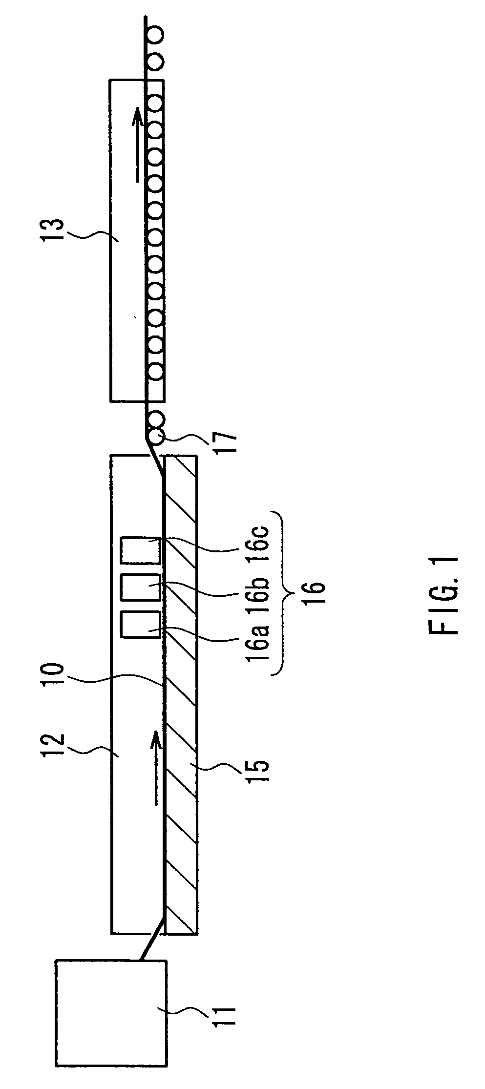
[0048] A 1-mm thick aluminosilicate glass sheet cut into a size of 150×150 mm was placed on a mesh belt and passed through a heating furnace to be heated to about 660° C. While transferring the heated glass sheet further, a mixed gas composed of tin tetrachloride (vapor), water vapor, hydrogen chloride, and nitrogen was supplied from a coater installed above the transfer line so as to form, on the glass, a thin film (buffer layer) having a film thickness of 110 nm and composed of tin oxide (SnO2) at a film deposition rate of 2210 nm / min. A plurality of such glasses for which the process was completed up to the buffer layer were prepared. After annealing the glass sheet, it was again placed on the mesh belt and was passed through the heating furnace to be heated to about 660° C. The heated glass sheet was further transferred, and a mixed gas composed of 2.1 mol % tin tetrachloride (vapor), 62.3 mol % water vapor, 0.1 mol % hydrogen chloride, nitrogen, and hydrogen fluoride was suppli...

example 2

[0051] A buffer layer was formed on a glass prepared in a similar manner to Example 1, under the same conditions as those in Example 1. This glass sheet again was placed on the mesh belt and was passed through the heating furnace to be heated to about 660° C. While transferring the heated glass sheet further, a mixed gas composed of 2.6 mol % tin tetrachloride (vapor), 79.9 mol % water vapor, 0.79 mol % hydrogen chloride, nitrogen, and hydrogen fluoride was supplied from a coater installed above the transfer line to form on the buffer layer a transparent conductive film (thin film containing a crystalline metal oxide as the main component) having a film thickness of 1700 nm and composed of fluorine-containing tin oxide (SnO2:F) at a film deposition rate of 11400 nm / min. Hydrogen chloride was supplied by mixing it, in advance, with water vapor that had not yet been mixed with tin tetrachloride. The mole ratio of hydrogen chloride to tin tetrachloride was 0.3. The gap between the coat...

example 3

[0054] A buffer layer was formed on a glass prepared in a similar manner to Example 1, under the same conditions as those in Example 1. This glass sheet was again placed on the mesh belt and was passed through the heating furnace to be heated to about 660° C. While transferring the heated glass sheet further, a mixed gas composed of 2.6 mol % tin tetrachloride (vapor), 80.1 mol % water vapor, 0.53 mol % hydrogen chloride, nitrogen, and hydrogen fluoride was supplied from a coater installed above the transfer line to form on the buffer layer a transparent conductive film (thin film containing a metal oxide as the main component) having a film thickness of 1650 nm and composed of fluorine-containing tin oxide (SnO2:F) at a film deposition rate of 10800 nm / min.

[0055] Hydrogen chloride was supplied by mixing it, in advance, with water vapor that had not yet been mixed with tin tetrachloride. The mole ratio of hydrogen chloride to tin tetrachloride was 0.2. The gap between the coater an...


PUM

PropertyMeasurementUnit
Speedaaaaaaaaaa
Deposition rateaaaaaaaaaa
Molar ratioaaaaaaaaaa

Abstract

The present invention provides a method of forming a thin film containing a metal oxide as the main component, the film thickness of which is relatively uniform, at a high film deposition rate over a wide area and over a long time. The present invention is a method for forming a thin film containing a metal oxide as the main component on a substrate using a mixed gas stream containing a metal chloride, an oxidizing material, and hydrogen chloride, by a thermal decomposition method at a film deposition rate of 4500 nm / min. or greater, performing at least one selected from: 1) prior to mixing the metal chloride and the oxidizing material in the mixed gas stream, contacting hydrogen chloride with at least one selected from the metal chloride and the oxidizing material, and 2) forming a buffer layer in advance on a surface of the substrate on which the thin film containing a metal oxide as the main component is to be formed.

Description

TECHNICAL FIELD [0001] This invention relates to a method of forming, on a surface of a glass sheet or the like, a thin film containing a metal oxide as the main component using a thermal decomposition method. The invention also relates to a substrate provided with the thin film formed by this method. The invention further relates to a photoelectric conversion device using the substrate provided with the thin film. BACKGROUND ART [0002] A thin film containing a metal oxide such as tin oxide has the function of reflecting infrared rays. Since a glass sheet provided with this thin film reduces the total solar energy transmittance and does not allow the heat within rooms to escape to the outdoors, it is widely available in the market as a low-emissivity glass. This thin film also can exhibit the function of shielding electromagnetic waves. A known method for manufacturing a glass sheet of this kind is such that a thin film of a metallic compound is formed on a high temperature glass su...

Claims


Application Information

Patent Timeline
IPC IPC(8): B60R16/02C03C17/245C03C17/34C23C16/02C23C16/40C23C16/54H01B7/08H01L31/18
CPCB60R16/0207Y10T428/26C03C17/3417C03C17/3452C03C2217/211C03C2217/241C03C2218/15C23C16/0272C23C16/0281C23C16/407C23C16/545H01B7/08H01L31/1884Y02E10/50C03C17/245
Inventor FUJISAWA, AKIRAARAI, DAISUKEICHIKI, KIYOTAKASUEYOSHI, YUKIOYAMAMOTO, TORUOTANI, TSUYOSHI
Owner NIPPON SHEET GLASS CO LTD
Learn More