Unfortunately, most discrete opto-electronic emitters exhibit a characteristic contravening to the goal of reduced internal
operating temperature.
However, increased power in devices with finite (positive, non-zero)
thermal resistance results in elevated internal operating temperatures.
Without these attributes, the use of LEDs becomes cost prohibitive or otherwise unattractive from a quality standpoint for most high-volume applications.
Hand
soldering suffers from inconsistency and high cost.
Mechanical connection schemes are expensive, bulky, and generally ill-suited for large numbers of electrical connections in many circuits.
Conductive adhesives such as silver-laden epoxies may be used to establish electrical connections on some circuit assemblies, but these materials are more costly and expensive to apply than solder.
Spot
soldering with lasers and other selective-solder techniques are highly specialized for specific configurations and applications and may disrupt flexible manufacturing procedures preferred in automated
electronic circuit assembly operations.
The
impact of this property is far reaching, because these solder operations can introduce large thermal stresses into an
electronic component sufficient to degrade or destroy the component.
The problem instead is the ability of these leads to conduct heat along their length into the encapsulated body of the device.
This can harm the somewhat delicate encapsulation, encapsulated wire bonds, die attach and
chip.
This phenomenon represents one of the fundamental limitations of low-cost, opto-electronic
semiconductor devices today.
This deformation from
polymer phase transition and
thermal expansion in encapsulants can generate mechanical stress and cumulative fatigue severe enough to damage a discrete
semiconductor device, resulting in poor performance of the device and a latent predisposition toward premature field failure.
Such damage typically consists of: 1) fatigue or fracture of electrical wire bonds (at the
chip bond pads or at the
lead frame); 2) partial
delamination or
decomposition of die-attach
adhesive; 3) micro-fracture of the
chip itself; and 4) degradation of the device encapsulant, especially near the entry points of the leads into the encapsulant, and a compromised ability to seal out
environmental water vapor,
oxygen, or other damaging agents.
However, the need for
optical transparency in encapsulants for opto-electronic emitters and receivers obviates use of most high-performance
polymer-filler blends, ceramics and composites that are suitable for non-optical semiconductors.
While useful, this has only partially alleviated the problems noted—the newest materials in use still fall 50 degrees C. or more short of parity with conventional non-optical
semiconductor encapsulation materials.
While effective at protecting prior art devices from thermal transients associated with soldering, there are limits to this approach, particularly in the application of high power semiconductor opto-electronic emitters.
Greater
thermal resistance in the solderable pins of these devices, necessary to protect the device from the transient thermal effects of soldering operations, therefore causes a higher
internal temperature rise within the encapsulated device body during operation.
As previously discussed, severe consequences will result if the device
internal temperature rises substantially above the encapsulant Tg value.
Above this temperature, the Cte of the encapsulant typically increases very rapidly, producing great thermo-mechanical stress and cumulative fatigue at the LED wire bond and die attach.
Since the emitted flux of semiconductor optical emitters are typically proportional to the
electrical current passed through them, limitations upon maximum
electrical current also create limitations on flux generated.
Other prior art devices have avoided these constraints, but have achieved high performance only by ignoring the needs of standardized, automated electronic
assembly operations and adopting configurations incompatible with these processes.
Still other prior art devices have achieved high performance by employing unusually expensive materials, sub-components, or processes in their own construction.
While relevant for certain high-cost
aerospace and
telecommunications applications (where component cost is not a significant concern), such devices require expensive materials and unusual
assembly processes.
This results in high cost and restricted manufacturing capacity—both of which effectively preclude the use of such components in
mass-market applications.
These devices are complex and typically involve insulated pin and header construction and / or include
specialty sub-components such as
ceramic isolation sheets within them.
This configuration, however, may complicate integration of such components with electronic circuits having higher complexity—such circuits are conventionally made using printed circuit boards, automated
insertion equipment, and wave or reflow solder operations.
However, there are several significant problems with this configuration that inhibit its broader use.
The
package geometry of the SuperFlux
package renders it incompatible with conventional high-speed THD radial or axial
insertion machinery or by SMT chip shooters known to the present inventors.
Instead, it must be either hand-placed or placed by expensive, slow, robotic odd-form
insertion equipment.
The SuperFlux
package geometry is configured for use as an “end-on” source only—no readily apparent convenient lead-bend technique can convert this device into a 90-degree “side-looker” source.
The moderate thermal resistance of the solderable pins of this device and relatively low
heat capacity may leave it vulnerable to damage from poorly controlled solder processes.
It may be inconvenient or costly for some
electronic circuit manufacturers to control their soldering operations to the degree needed for this configuration.
Finally, there is no convenient mechanism known to the inventors to outfit a SuperFlux package with a conventional active or passive
heat sink.
A principle factor impeding further application of these and other LED devices in signaling, illumination and display applications is that there is not currently available a device that has a high
power capability with high emitted flux where the device is easily adaptable to automated insertion and / or
mass-soldering processes.
These limitations have either impeded the practical use of LEDs in many applications requiring
high flux emission, or they have mandated the use of arrays of many LED components to achieve desired flux emission.
Conventional “5 mm” or “T 1¾” devices have a high thermal resistance, typically in excess of 240 degrees C. per
watt and usually are limited by clear encapsulation materials that lead to unreliability if the emitter in the device is operated continuously, routinely or cyclically above 130 degrees C.
This means that the device power must be limited to approximately 0.18 W. With a reasonable design tolerance of 33 percent to accommodate manufacturing variances, the practical reliable power limit of this device must be approximately 0.12 W. This is not a lot of power, and the emitted flux of these devices is thus limited.
As with “5 mm” or “T 1¾” devices, SuperFlux or Piranha devices usually are limited by clear encapsulation materials that lead to unreliability if the emitter in the device is operated continuously, routinely, or cyclically above 130 degrees C.
This means that the device power must be limited to approximately 0.3 W. Because these devices are attached subsequently with thermally stressful wave or other solder operations, and because their thermal resistance from lead to junction is reduced, they are more susceptible to damage during
processing into circuits.
Thus, a higher design tolerance of 40 percent should be used to accommodate manufacturing variances and increased susceptibility, and the practical reliable power limit of this device must be approximately 0.18 W. This is a substantial increase (33 percent) compared to “5 mm” or “T 1¾” devices, it still is not a lot of power and the emitted flux of these devices is thus also limited.
As with “5 mm” or “T 1¾” or SuperFlux, Piranha, or SnapLED devices usually are limited by clear encapsulation materials that lead to unreliability if the emitter in the device is operated continuously, routinely, or cyclically above 130 degrees C.
This means that the device power must be limited to approximately 0.45 W. As noted above, because the thermal resistance of these devices from lead to junction is so low, they cannot be soldered by conventional means without being damaged.
This severely limits their utility, but they still are suitable for some applications.
Because these devices are attached subsequently with mechanically stressful clinching operations, they remain susceptible to damage during
processing operations.
Thus, a higher design tolerance of 40 percent should be used to accommodate manufacturing variances and potentially increased
processing damage susceptibility, and the practical reliable power limit of this device must be approximately 0.27 W. This is a significant increase compared to “5 mm” or “T 1¾” or SuperFlux or Piranha devices, but it still is not a lot of power (and is achieved at a sacrifice in conventional
solderability).
Such a design and process are difficult and expensive to execute with high yield and high quality.
Accumulated variances would be excessive from the multistage molding scheme, interrupted by die and
wire bonding.
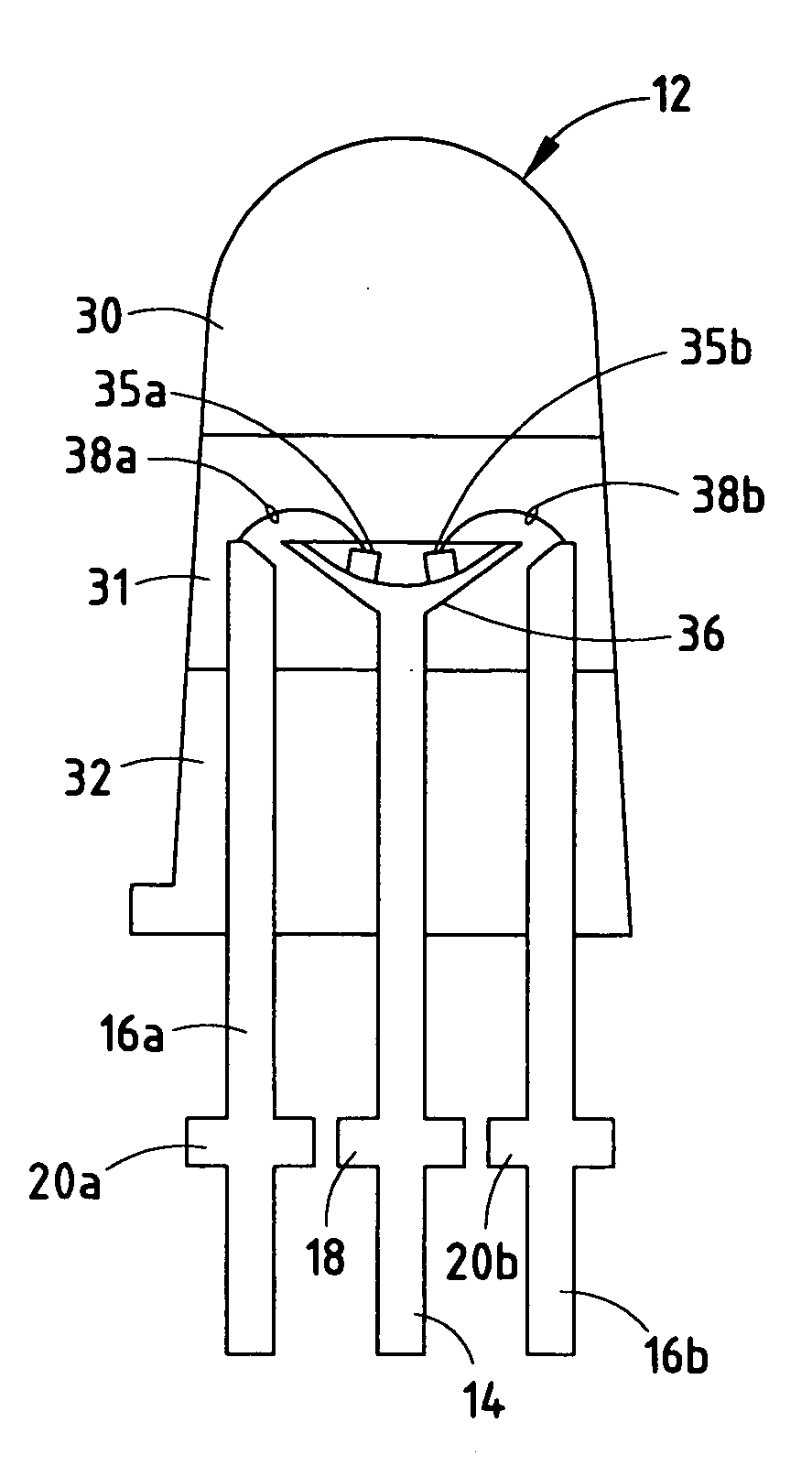
An additional problem faced by designers of conventional LED devices is that the wire bond used to join one of the LED leads to the LED chip can break or lose contact with the lead or the chip.
Such failure can occur, for example, due to shear forces that are transferred to the wire bond through the encapsulant or
thermal expansion / contraction of the encapsulant around the wire bond.
The other forms of radiation emitters mentioned above also experience performance degradation, damage, increased
failure probability, or accelerated decay if exposed to excessive operating temperatures.

