

Ultraviolet activated antimicrobial surfaces
- Summary
- Abstract
- Description
- Claims
- Application Information
AI Technical Summary
Benefits of technology
Problems solved by technology
Method used
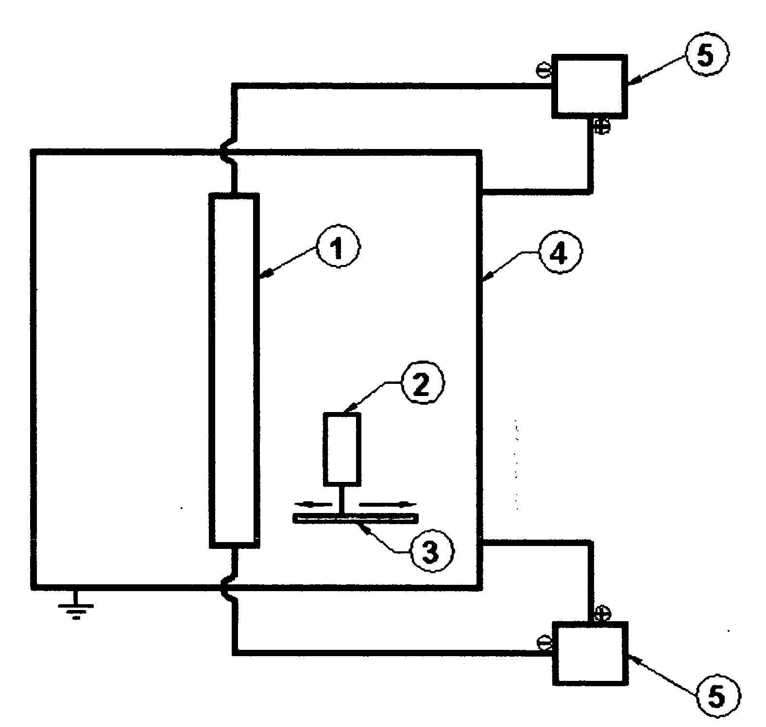
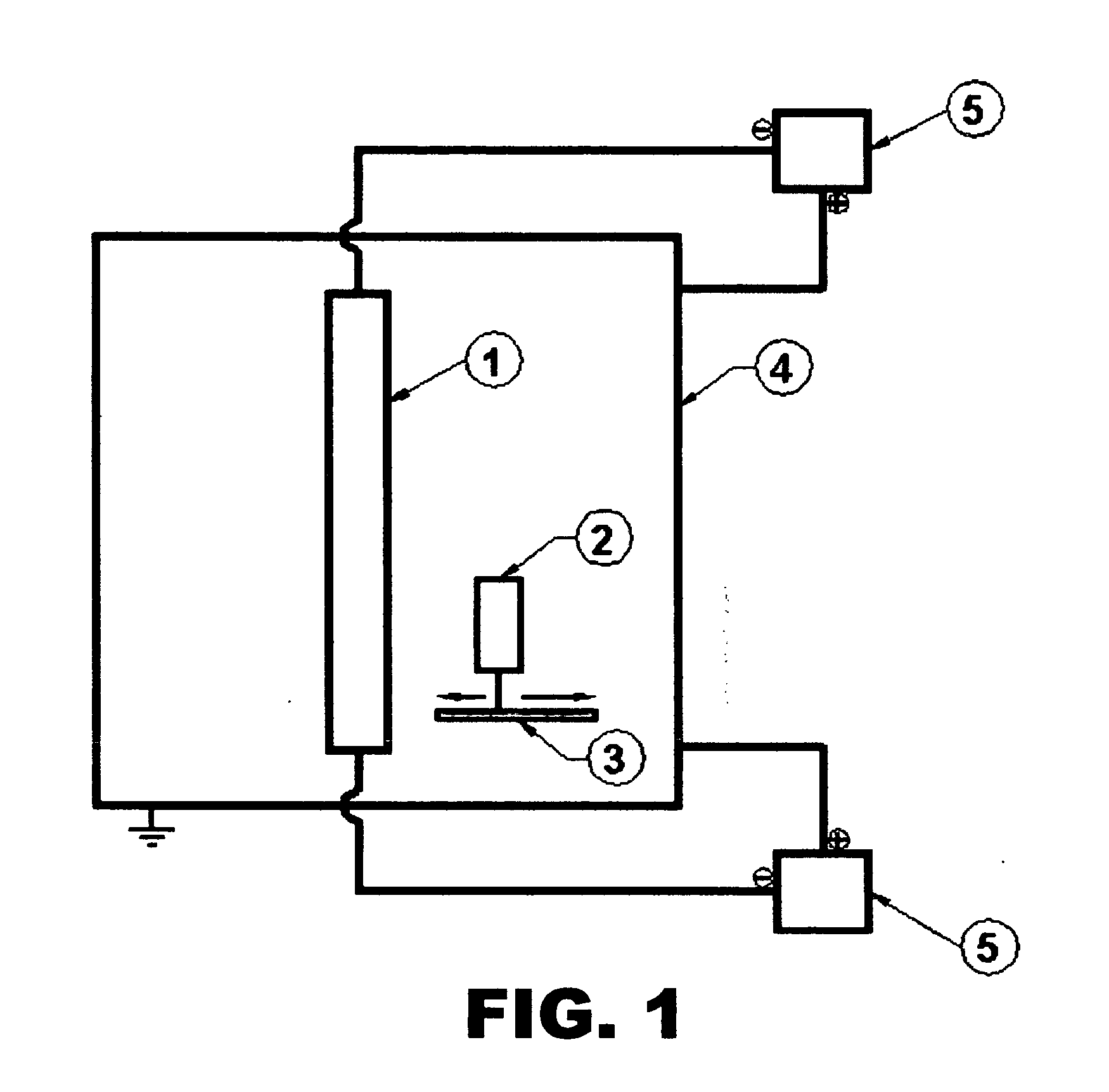
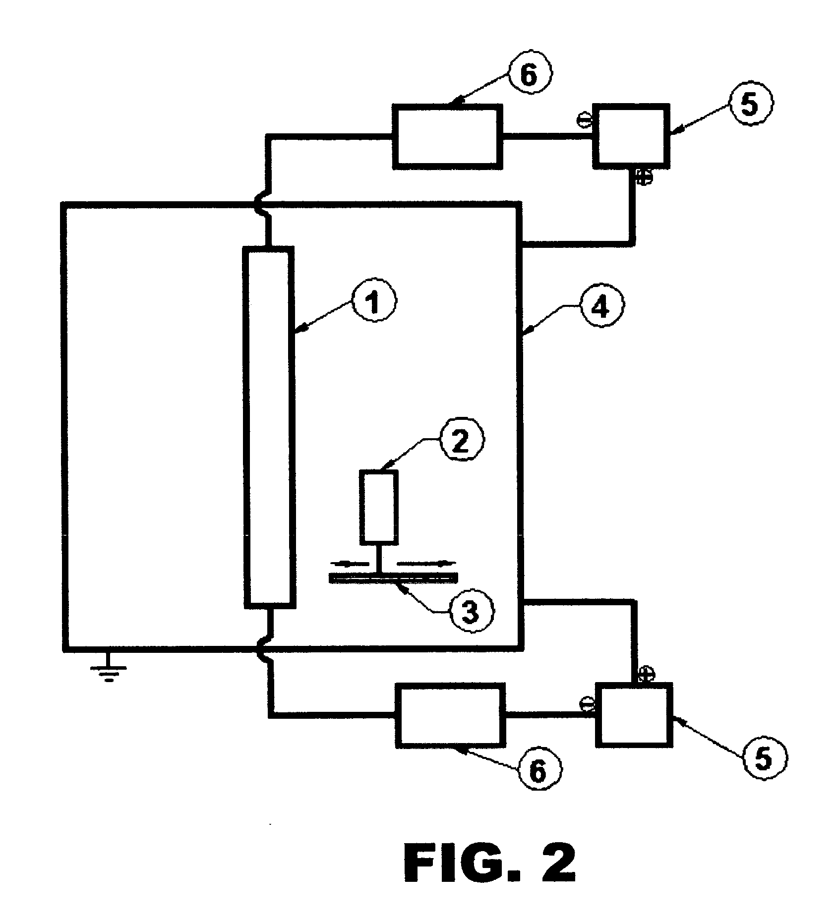
Image

Examples
example 1
Antibacterial Activity of Sputtered Silver Coating on Latex
[0066]This example was performed in accordance with the coating and testing procedures described in U.S. Pat. No. 5,454,886 (the '886 patent). The method and testing were performed in accordance with the procedure detailed in Example 6 of the '886 patent.
[0067]Silver metal was deposited on 2.5 cm sections of a latex Foley catheter using a magnetron sputtering facility. Operating conditions were as follows; the deposition rate was 200 Å per minute; the argon working gas pressure was 30 m Torr; and the ratio of temperature of substrate to melting point of the coating metal silver, T / Tm was 0.30. In this example the angles of incidence were variable since the substrate was round and rough. That is the angles of incidence varied around the circumference and, on a finer scale, across the sides and tops of the numerous surface features. The anti-microbial effect was tested by a zone of inhibition test, identical to the test descri...
example 2
Antibacterial Activity of Sputtered Silver Coating over Teflon® on Latex
[0069]This example follows the procedures reported for preparing a Teflon®-coated latex catheter coated by DC magnetron sputtering in accordance with Example 7 in U.S. Pat. No. 5,454,886. Antimicrobial testing was performed with S. Aureus as described.
[0070]A Teflon coated latex Foley catheter was coated by DC magnetron sputtering 99.99% pure silver on the surface under the following conditions: 0.5 kW power, 40 mTorr Ar / O2, 20° C. initial substrate temperature, a cathode / anode distance of 100 mm, and a final film thickness of 300 nm. The working gases were commercial Ar and 99 / 1 wt % Ar / O2.
[0071]The anti-microbial effect of the coating was tested by a ZOI as described in Example 7 of the '886 patent. Mueller Hinton agar was dispensed into Petri dishes. The agar plates were allowed to surface dry prior to being inoculated with a lawn of Staphylococcus aureus ATCC#25923. The inoculant was prepared from Bactrol Di...
example 3
Sputtered Antibacterial Silver Coating
[0073]This example was performed in accordance with the procedure described in Example 11 in the '866 patent. Conditions used for this example included: RF magnetron power of 0.5 kW, 40 mTorr pressure, 100 mm anode / cathode distance, and 20° C.
[0074]When a working gas of argon and 20 wt % oxygen was used to sputter anti-microbial coatings under the conditions listed above, the zones of inhibition ranged from 0 to 2 mm, in contrast to the ZOI of 6 to 12 mm reported in the '866 patent Example 11.
PUM
| Property | Measurement | Unit |
|---|---|---|
| Thickness | aaaaa | aaaaa |
| Thickness | aaaaa | aaaaa |
| Thickness | aaaaa | aaaaa |
Abstract
Description
Claims
Application Information