Electrochemical Patterning on Multi-Channel Microelectrode Array for Biosensing Applications

a microelectrode array and multi-channel technology, applied in the field of new electrode array technology, can solve the problems of large complexity, lack of suitable methods and means, time-consuming, expensive, etc., and achieve the effect of high selectivity

Inactive Publication Date: 2008-05-15
ETH TRANSFER +1
View PDF0 Cites 6 Cited by
  • Summary
  • Abstract
  • Description
  • Claims
  • Application Information

AI Technical Summary

Benefits of technology

[0021]In the case of electrically conductive indium tin oxide (ITO) microelectrodes, surrounded by an insulating silicon oxide (SiO2) background and an adlayer of fluorescently labeled PLL-g-PEG/633, Confocal Laser Scanning Microscopy (CLSM) images revealed that an external electrical polarization at +1800 mV (reference to silver electrode) results in the electrochemical desorption of the PLL-g-PEG/633 adlayer from the selected ITO microelectrodes, without affecting the passive backfill on the unpolarized ITO and the insulating SiO2. Subsequently the electronically activated microelectrodes can be surface functionalized with different macromolecules such as optionally functionalized (in partic

Problems solved by technology

Considering that proteins are complex three-dimensional molecules with a larger library compared to genes, huge challenges remain to elucidate the sequence and function and interactions of every encoded protein.
However, hitherto there does not yet exist a suitable method and means for investigating protein involving interactions, in particular also since methods suitable for producing nucleic acid microarrays

Method used


Image

  • Electrochemical Patterning on Multi-Channel Microelectrode Array for Biosensing Applications
  • Electrochemical Patterning on Multi-Channel Microelectrode Array for Biosensing Applications
  • Electrochemical Patterning on Multi-Channel Microelectrode Array for Biosensing Applications

Examples


example 1

Passivation and Electronic Activation of Microelectrode Array

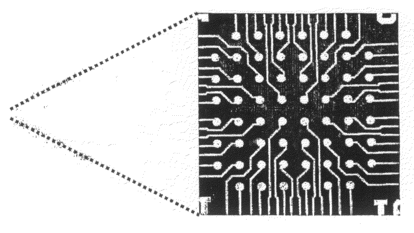
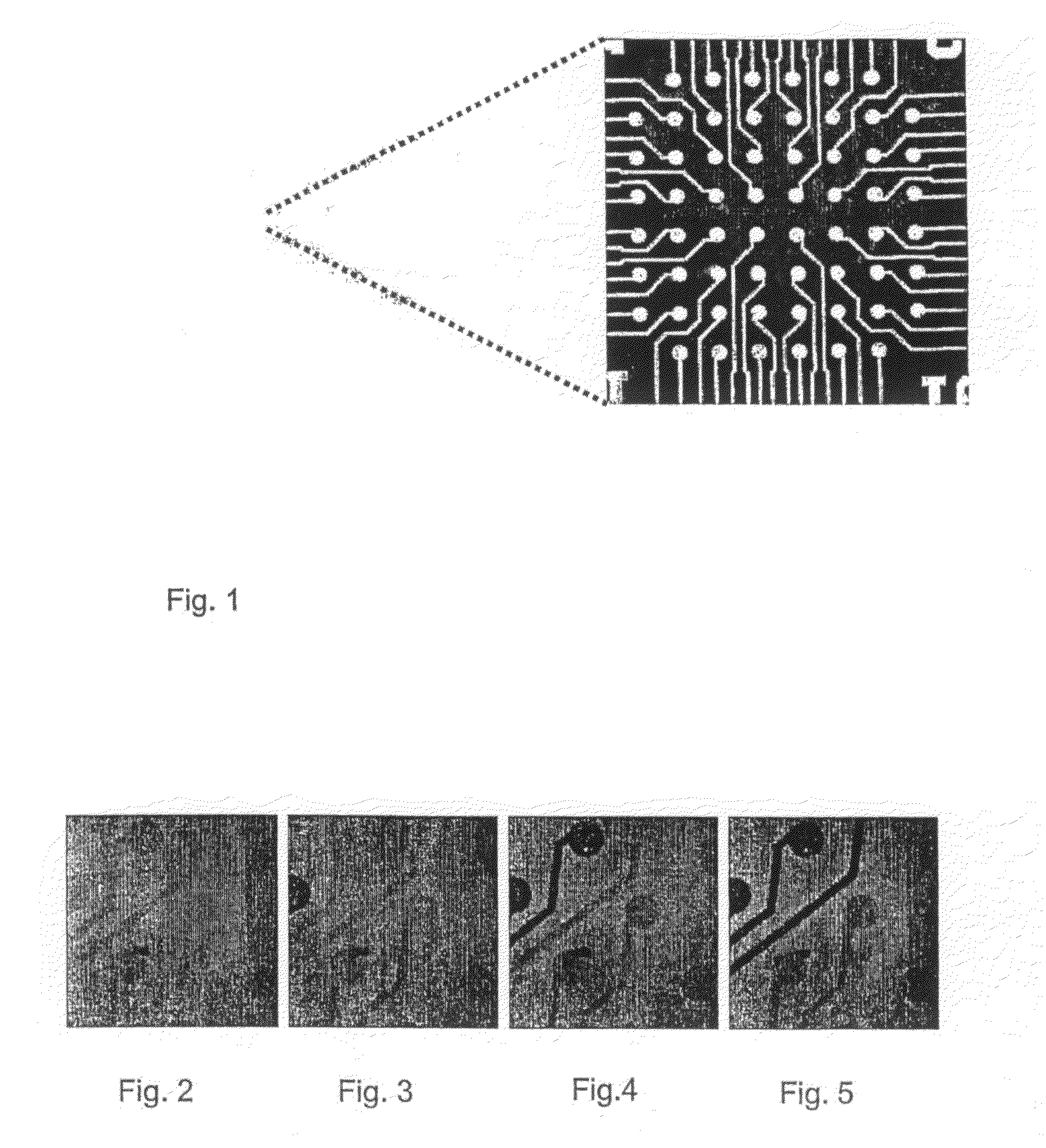
[0080]PLL-g-PEG / 633 solution was adsorbed in the flow cell onto the microelectrode array platform at an open circuit potential for 60 min. FIG. 2 is a confocal image showing the uniform adsorption of the fluorescence-labeled PLL-g-PEG / 633 onto the surface of the microelectrode array at open circuit potential. The microelectrodes are slightly darker in comparison to the surrounding silicon oxide region, primarily due to the quenching effects of the ITO. A photo-bleached region on an unaddressed PLL-g-PEG / 633 coated microelectrode revealed the background signal of the underlying platform.

[0081]By applying an external electric field of +1800 mV (reference to a silver electrode) on the individually selected ITO microelectrode(s), the loss of fluorescence signal on it(them) could be shown to be within less than 60 seconds (FIGS. 2 to 5). The loss of the fluorescence signal is due to the electrochemical desorption of the protein...

example 2

Selective Surface Functionalization with Fluorescence-Labeled Polymer, poly(L-lysine)-grafted-poly(ethylene glycol) (PLL-g-PEG / 488)

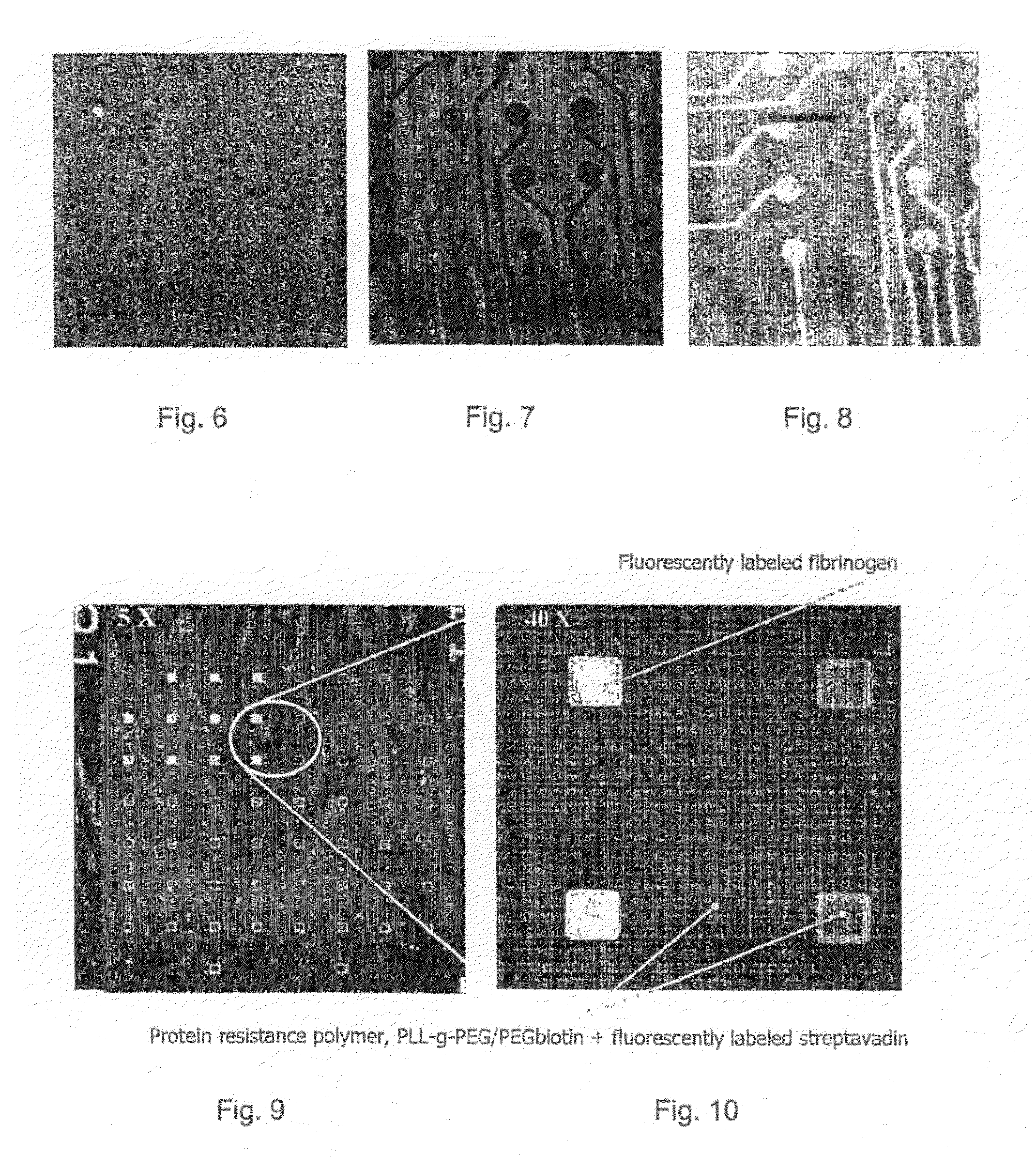
[0082]The microelectrode array is uniformly exposed to PLL-g-PEG / 633 at open circuit potential for 60 min and rinsed with HEPES 2 solution (see FIG. 6). Then the protein-resistant adlayer is completely removed from the surface of selected ITO microelectrodes by an external electrical polarization at +1800 mV (reference to silver electrode) applied to them (see dark electrodes in FIG. 7). Afterwards, the microelectrode array is exposed to PLL-g-PEG / 488 for 60 min which covered the bare and electronically activated ITO (see clear electrodes in FIG. 8).

example 3

Selective Surface Functionalization with Fluorescent-Labeled Proteins

[0083]As adlayer the biotinylated polymer, PLL-g-PEG / PEGbiotin was adsorbed on the microelectrode array as a backfill. By applying a voltage of +1800 mV (reference to silver electrode) the protein resistant polymer could be removed from a selected region of microelectrodes. The microelectrode array was then exposed to fluorescent-labeled human fibrinogen which was found to adsorb specifically onto the electronically activated ITO microelectrodes (clear spots in the confocal microscopy images, FIGS. 9 and 10). The protein resistant backfill prevented non-specific adsorption of the fibrinogen onto the surrounding region. Then fluorescent-labeled streptavidin which has a strong binding affinity to biotin was introduced into the microelectrode array which resulted in adsorbance of fluorescent-labeled streptavidin over the whole surface still functionalized with PLL-g-PEG / PEGbiotin, i.e. the whole surface except for the...


PUM

PropertyMeasurementUnit
Timeaaaaaaaaaa
Electric potential / voltageaaaaaaaaaa

Abstract

Described is a method for electrochemically patterning a microelectrode array (MEA) with at least two different kinds of macromolecules. Said method comprising the steps of: providing a platform with a surface that comprises individually addressable conductive microelectrode surfaces; covering said platform surface with an adlayer of resistant polymer; desorbing said adlayer from a first kind of conductive microelectrodes intended for the selective adsorption of a first kind of macromolecules, in particular proteins, by applying a potential; subjecting the desorbed surfaces to the first macromolecule under conditions such that said first macromolecule adsorbs to said desorbed surfaces, and repeating the desorption/adsorption steps with a second or further kind of macromolecules until all kinds of desired macromolecules are adsorbed. A microchip array produced by the inventive method is also described. Such chip arrays can be used to study a large diversity of biological interactions, e.g. protein-protein interactions, protein-cell interactions, protein-nucleic acid interactions, etc.

Description

CROSS REFERENCES TO RELATED APPLICATIONS[0001]This application claims the priority of European patent application no. 04022317.4, filed Sep. 20, 2005, the disclosure of which is incorporated herein by reference in its entirety.TECHNICAL FIELD[0002]The present invention concerns a novel technique to provide a biologic electrode array, in particular a chip array that includes an array of electrodes, in particular a microarray / biochip for measuring interactions of non-nucleic acid biological compounds / products with analytes and such chip as well as its use in analytics.BACKGROUND ART[0003]One of the most interesting features commonly found in DNA microarrays, proteomics biochips and immunoarrays involves surface patterning which strategically integrates both surface chemistry and specific biomolecular immobilization. Over the years, different bioanalytical approaches towards achieving high sensitivity, specific selectivity and efficient throughput, especially in the field of biosensing...

Claims


Application Information

Patent Timeline
IPC IPC(8): C12Q1/68H01L21/00C12M1/34G01N33/543
CPCB01J19/0046B01J2219/00286B01J2219/00495B01J2219/00531B01J2219/00596B01J2219/00608B01J2219/0074B01J2219/00617B01J2219/00635B01J2219/00659B01J2219/00713B01J2219/00722B01J2219/00725B01J2219/00612
Inventor VOROS, JANOSTEXTOR, MARCUSTANG, CLARENCEKELLER, BEAT
Owner ETH TRANSFER
Why Eureka
Try Eureka