
Solar Cell Having Tree-Like Nanostructure and Method for Preparing the Same

Inactive Publication Date: 2009-02-12
NAT TAIWAN UNIV
View PDF2 Cites 30 Cited by
  • Summary
  • Abstract
  • Description
  • Claims
  • Application Information

AI Technical Summary

Benefits of technology

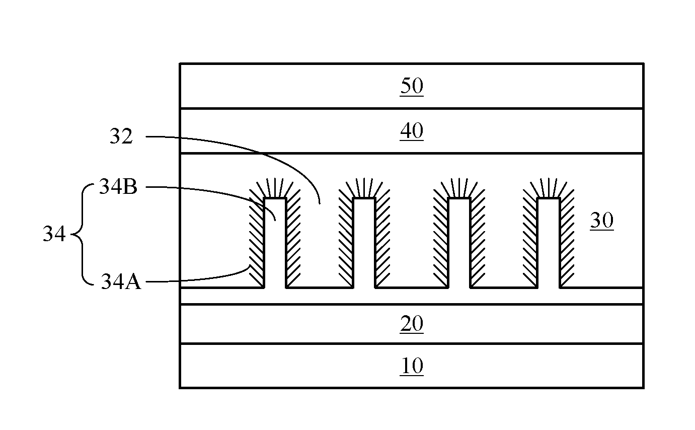
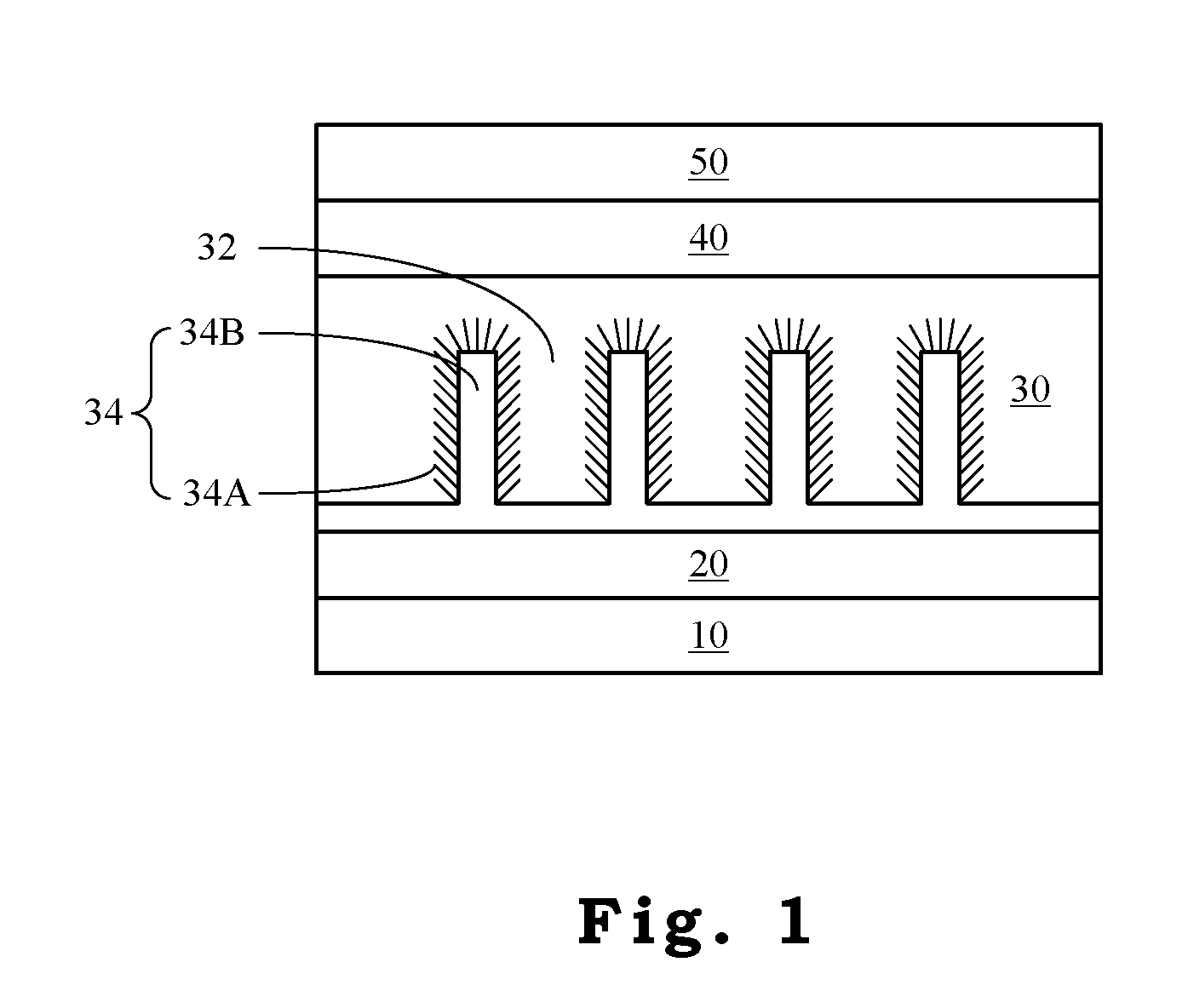
[0008]One objective of the present invention is to use a tree-like nanostructure array and conjugate polymer fillers to form a photo-active layer. Since the in-situ synthesis trunk part provides a long straight transport pathway to transport electrons and the large contact area between the branch part and the conjugate polymer filler provides electron-hole separation, the energy conversion efficiency of a solar cell can be increased multiple times. Therefore, this present invention does have the economic advantages for industrial applications.

Problems solved by technology

However, the cell efficiency of a polymer solar cell is still low.
However, as the nanoparticle concentration is high, coagulation between nanoparticles occurs and the area of the interface between the electron acceptor and the electron donor is thereby decreased to further lower the efficiency of electron-hole separation and the quantum efficiency of energy transfer.
On the other hand, as the properties of nanoparticles are significantly different from those of conjugate polymers, directly physically blending these two substances will result in serious phase separation so that the exciton generated by light excitation can not have good charge transfer to thereby lower the efficiency of energy conversion of the device.
Even though the nanoparticles and the polymers are well blended, the charge transport speed is still limited due to the non-linear transport pathway.

Method used


Image

  • Solar Cell Having Tree-Like Nanostructure and Method for Preparing the Same
  • Solar Cell Having Tree-Like Nanostructure and Method for Preparing the Same
  • Solar Cell Having Tree-Like Nanostructure and Method for Preparing the Same

Examples


example 1

Forming Zinc Oxide Trunk Part Array

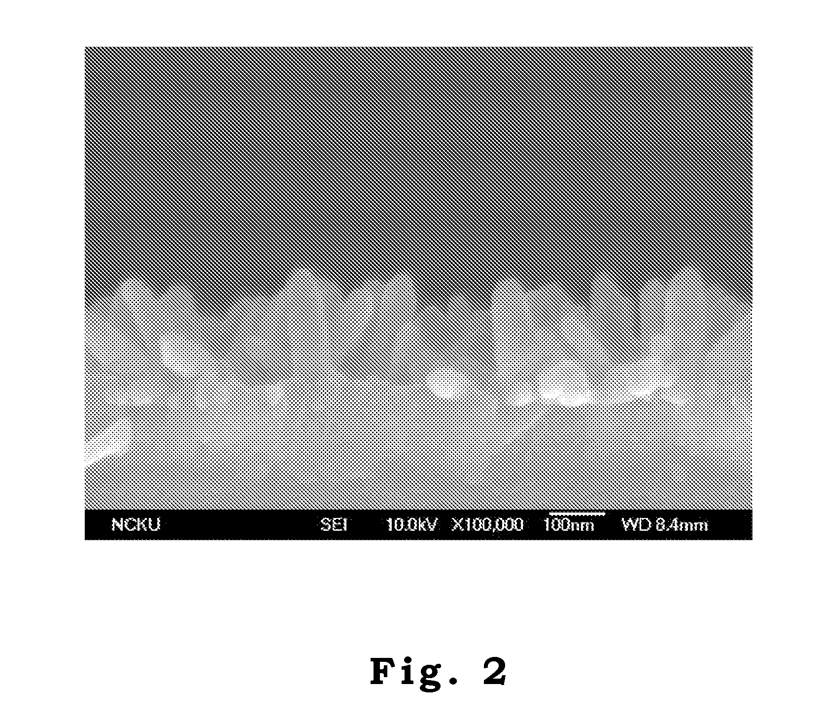
[0037]A conducting Au metal layer with a thickness of about 10 nm is formed on an ITO glass substrate by DC sputtering. Then, ZnO trunk part arrays are grown on the Au-coated ITO substrate by pulsed current electrolysis method at 80° C. If the ITO cathode is used as the working electrode in the current electrolysis method to in-situ form the trunk parts from ITO cathode, the trunk parts can not be uniformly formed. Thus, a conducting metal layer is coated as the working electrode in order to have the distribution of charges uniform so as to in-situ form the trunk parts regularly. The substrate, a platinum wire and an Ag / AgCl electrode are utilized as the working, the counter and the reference electrodes, respectively, in the electrochemical system. A 0.0025M aqueous solution of Zn (NO3)2 is employed to be the electrolyte. A pulsed wave with a pulse length and a pulse period of 0.01 and 0.1 s, respectively, are used for the growth of ZnO trunk part ...

example 2

Forming Titanium Oxide Branch Part

[0038]High aspect ratio anatase TiO2 branch parts are synthesized by the sol-gel method with hydrolysis of titanium tetraisopropoxide as described in Nanotechnology, 17, 5781, (2006) by Y. T. Lin, T. W. Zeng, W. Z. Lai, C. W. Chen, Y. Y. Lin, Y. S. Chang, W. F. Su. FIG. 3 shows the high-resolution transmission electron microscopy (HRTEM) image of TiO2 branch parts where the dimension of TiO2 branch parts is about 5 nm in diameter and 20 nm in length. The P3HT solution is prepared by dissolving conjugate polymer P3HT (Aldrich, USA) in chloroform. The mixture solution with 50 wt % TiO2 branch parts is obtained by mixing the required amount of TiO2 branch parts with the P3HT solution. By spin coating, the mixture solution is infiltrated in the cavities between ZnO trunk part arrays for TiO2 branch parts to deposit on the ZnO trunk parts. The conjugate polymer P3HT has hole transport and light absorbing functions.

example 3

Preparing a Solar Cell Having a Tree-Like Nanostructure

[0039]In air, a PEDOT:PSS layer with a thickness of 50 nm is coated on the device formed in example 2 by spin coating. PEDOT:PSS material has high conductivity and thus can reduce interface resistance. In addition, it can fill up gaps to have smooth surface. After the PEDOT:PSS coating process is finished, it is baked at 120° C. under vacuum for 6 hours. Finally, at a pressure of 2×10⁻⁶ torr, gold (Au) is evaporated to form a gold layer as the anode.

Result 1

[0040]The time-resolved photoluminescence spectra are obtained by a time-correlated single photon counting (TCSPC) spectrometer (Picoquant, Inc.). A pulse laser (375 nm) with an average power of 1 mW operating at 40 MHz with duration of 70 ps is used for excitation. The current-voltage measurement for the device prepared in example 3 is obtained by using a solar simulator (Oriel Inc.) with the A.M.1.5 filter. Transient photocurrent measurements are performed by a frequency-tr...


PUM

PropertyMeasurementUnit
Lengthaaaaaaaaaa
Diameteraaaaaaaaaa
Diameteraaaaaaaaaa

Abstract

The present invention discloses a solar cell having a multi-layered structure that is used to generate, transport, and collect electric charges. The multi-layered nanostructure comprises a cathode, a conducting metal layer, a photo-active layer, a hole-transport layer, and an anode. The photo-active layer comprises a tree-like nanostructure array and a conjugate polymer filler. The tree-like nanostructure array is used as an electron acceptor while the conjugate polymer filler is as an electron donor. The tree-like nanostructure array comprises a trunk part and a branch part. The trunk part is formed in-situ on the surface of the conducting metal layer and is used to provide a long straight transport pathway to transport electrons. The large contact area between the branch part and the conjugate polymer filler provides electron-hole separation.

Description

BACKGROUND OF THE INVENTION[0001]1. Field of the Invention[0002]The present invention is generally related to a solar cell and a method for preparing the same, and more particularly to a solar cell having a tree-like nanostructure and a method for preparing the same.[0003]2. Description of the Prior Art[0004]At present, polymer solar cells attract great research interests because the various advantages compared to the traditional silicon-based solar cells. For example, the fabrication cost is low and it is easy to fabricate a cell with large area, transparent cell, and flexible cell, etc. However, the cell efficiency of a polymer solar cell is still low. Thus, developing a polymer solar cell with high efficiency becomes an important research target.[0005]The operating principle of polymer solar cells is as follows. When a polymer cell is irradiated by sun, the conjugate polymer in the polymer solar cell absorbs sunlight to have its electron in the highest occupied molecular orbital ...

Claims


Application Information

Patent Timeline
IPC IPC(8): H01L31/04B05D1/00C25D5/00H01L31/18
CPCH01G9/2036H01L31/022433H01L31/04H01L31/18Y02E10/549H01L51/4226H01L51/4233H01L51/4266H01L51/0036H10K85/113H10K30/152H10K30/151H10K30/352H10K30/50
Inventor SU, WEI-FANGCHEN, CHUN-WEIWU, JIH-JENLIN, YUN-YUE
Owner NAT TAIWAN UNIV
Learn More